Stepper Motors are fundamental components in precision motion control systems, widely used in 3D printers, CNC machines, robotics, and automation. One of the most common types of stepper motors encountered in these applications is the bipolar stepper motor, which typically features four wires. But why exactly do stepper motors have four wires, and what role do they play in the motor's performance and control? Let's dive into a comprehensive explanation.
Understanding the Basic Working Principle of Stepper Motors
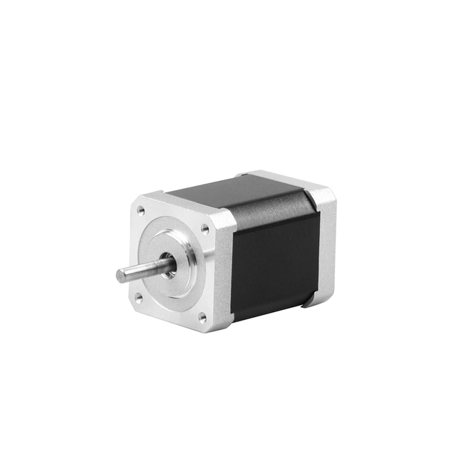
A stepper motor is a brushless, synchronous electric motor designed to move in precise, fixed angular steps. Unlike conventional DC motors that rotate continuously when voltage is applied, a stepper motor divides a full rotation into a series of discrete steps. This characteristic allows it to achieve high positional accuracy without requiring feedback sensors, making it ideal for robotics, CNC machinery, and 3D printing.
Inside the stepper motor, there are two main components: the stator (stationary part) and the rotor (moving part). The stator contains several electromagnetic coils arranged around the rotor. When electrical pulses are sent sequentially to these coils, they become magnetized and attract or repel the magnetic poles of the rotor. By carefully controlling the sequence of coil activation, the rotor moves incrementally, one step at a time.
Each pulse from the controller corresponds to one mechanical step, which translates to a specific angular movement — for example, 1.8° per step for a 200-step motor. By varying the rate and timing of these pulses, users can control both the speed and direction of the motor's rotation.
Additionally, modern stepper motors can operate in different stepping modes:
Full-step mode: Each step corresponds to a full rotor position.
Half-step mode: Alternates between full and half-step movements for smoother motion.
Microstepping: Divides steps into smaller increments for extremely smooth and precise motion control.
In essence, the working principle of a stepper motor is based on the synchronization between electrical pulse signals and mechanical rotation. This unique capability allows stepper motors to maintain position accurately even without an encoder, offering a simple yet powerful solution for applications requiring precise, repeatable motion control.
The Internal Structure: Coils and Phases
The internal structure of a stepper motor is what gives it the ability to move with such precision and control. At its core, a stepper motor is composed of two main parts — the stator and the rotor — which work together through a carefully designed arrangement of coils and magnetic phases.
1. The Stator
The stator is the stationary outer section of the motor. It contains several electromagnetic coils (also called windings) arranged in a circular pattern around the rotor. These coils are divided into groups known as phases, which are energized in a specific sequence to create a rotating magnetic field.
When a current flows through one of these coils, it generates a magnetic pole (north or south). By switching the current between different coils in a precise order, the stator's magnetic field moves around the rotor, causing it to rotate step by step.
2. The Rotor
The rotor is the rotating inner part of the motor, typically made of a permanent magnet or a soft iron core with magnetic teeth. It responds to the magnetic fields generated by the stator's coils. As the electromagnetic fields shift, the rotor's teeth align themselves with the magnetic poles of the stator, resulting in a precise incremental movement.
Depending on the motor design, the rotor can take one of three main forms:
Permanent magnet (PM) rotor: Uses permanent magnets for stronger torque and defined step angles.
Variable reluctance (VR) rotor: Has soft iron teeth that align with the magnetic field without magnets.
Hybrid rotor: Combines both PM and VR features for higher torque and better step accuracy.
3. Coils and Phases Explained
The phases of a stepper motor refer to independent sets of windings that can be energized separately. Each phase produces a magnetic field that interacts with the rotor. The most common configurations are:
Two-phase (bipolar): Contains two coils, each with two wires (four wires total).
Four-phase (unipolar): Has additional center taps, resulting in five or six wires.
Each coil (or phase) works in synchronization with the others. When the motor controller energizes one phase and then the next, the magnetic field shifts slightly, pulling the rotor forward by one step. Repeating this cycle continuously results in smooth rotational motion.
4. Relationship Between Coils and Step Resolution
The number of coils and magnetic teeth in the rotor determine the step angle — the amount of rotation per step. For example, a typical hybrid stepper motor might have 200 steps per revolution, meaning each step moves the rotor 1.8°. Increasing the number of stator poles or rotor teeth results in smaller step angles and finer resolution.
5. Importance of Coil Sequencing
The precise timing of how these coils are energized — known as phase sequencing — is critical. The motor driver sends electrical pulses to each phase in a specific order, ensuring smooth movement and accurate position control. Incorrect sequencing can cause vibration, loss of steps, or even motor stall.
In summary, the internal structure of a stepper motor — with its arranged coils and multiple phases — is the foundation of its ability to deliver precise, controlled motion. By energizing the coils in an exact pattern, the motor converts electrical pulses into mechanical steps, achieving accurate positioning that is essential in applications such as CNC machines, robotics, and precision automation systems.
Why Four Wires? Understanding the Bipolar Configuration
The presence of four wires in many stepper motors is directly linked to their bipolar configuration, one of the most efficient and widely used designs in motion control systems today. Understanding why stepper motors have four wires requires an exploration of how their internal coils are structured and how electric current flows through them to create precise, controlled motion.
1. The Basics of the Bipolar Stepper Motor
A bipolar stepper motor consists of two independent electromagnetic coils, also known as phases. Each coil is made of tightly wound copper wire, and both coils are required to generate the magnetic fields that move the rotor. In a bipolar setup, current must be able to flow in both directions through each coil to create alternating magnetic poles.
This bidirectional current flow allows the magnetic polarity of each coil to reverse, enabling the rotor to move forward or backward depending on the current sequence.
The four wires of a bipolar stepper motor correspond to the two ends of each of the two coils:
Coil A: Wire 1 and Wire 2
Coil B: Wire 3 and Wire 4
There are no center taps in this configuration — unlike in a unipolar motor — meaning each coil is used in its entirety. This leads to higher torque output and improved electrical efficiency.
2. How the Four Wires Work Together
Each pair of wires in a four-wire stepper motor belongs to a single coil. The motor driver alternates the polarity of the current in each coil in a specific sequence. When current flows in one direction through Coil A, it generates a magnetic field with a specific polarity (e.g., north at one end, south at the other). When the driver reverses the current, the magnetic poles also reverse.
By coordinating this polarity change between Coil A and Coil B, the driver produces a rotating magnetic field that makes the rotor move step by step.
For example:
Step 1: Coil A energized (north-south)
Step 2: Coil B energized (north-south)
Step 3: Coil A energized (south-north)
Step 4: Coil B energized (south-north)
Repeating this cycle continuously results in smooth, continuous rotation of the motor shaft.
3. Advantages of the Four-Wire Bipolar Configuration
The four-wire bipolar stepper motor offers several significant benefits compared to its unipolar counterparts with five or six wires.
a. Higher Torque Output
Because each entire winding is utilized, the bipolar motor can produce stronger magnetic fields. This results in greater torque for the same amount of current, making it ideal for demanding applications like CNC machinery, robotics, and industrial automation.
b. Greater Efficiency
With current flowing through the full coil length, the motor makes better use of electrical energy, minimizing heat loss and improving overall efficiency.
c. Simplified Wiring
Having just four wires simplifies the wiring process. Each coil only requires two connections, which makes installation easier and reduces potential wiring errors.
d. Enhanced Precision and Responsiveness
Bipolar motors are known for smooth movement and accurate step transitions. The ability to reverse current flow allows for finer control over position and torque, especially when using microstepping drivers.
4. Comparison: Bipolar (Four-Wire) vs. Unipolar (Six-Wire)
| Feature | Bipolar Stepper (Four-Wire) | Unipolar Stepper (Six-Wire) |
| Coil Configuration | Two coils without center taps | Two coils with center taps |
| Number of Wires | 4 | 5 or 6 |
| Current Direction | Reversible (requires H-bridge) | Fixed direction per coil half |
| Torque Output | Higher | Lower |
| Efficiency | High | Moderate |
| Driver Circuit | Slightly complex (H-bridge) | Simpler |
| Application | High torque, precision control | Lower torque, basic systems |
This comparison highlights why modern systems often prefer bipolar stepper motors — they deliver superior torque and performance, especially when driven by advanced microstepping drivers.
5. How to Identify the Four Wires
When working with a four-wire stepper motor, it’s important to determine which wires belong to which coil. This can easily be done using a multimeter:
Set the multimeter to the resistance (Ω) setting.
Measure between two wires — if you get a small resistance reading, those two belong to the same coil.
The remaining two wires will form the second coil.
Labeling them correctly is crucial before connecting to the driver. Incorrect wiring can cause the motor to vibrate, stall, or fail to rotate altogether.
6. Driving a Four-Wire Stepper Motor
A bipolar stepper motor driver is used to control current flow through each coil. These drivers employ H-bridge circuits that can reverse current direction through each winding.
By sending electrical pulses in a precise order, the driver energizes the coils alternately, causing the rotor to move step-by-step. Modern drivers also support microstepping, which divides each full step into smaller steps, resulting in smoother motion, less vibration, and higher positioning accuracy.
7. Common Applications of Four-Wire Stepper Motors
Due to their high torque density and excellent precision, four-wire bipolar stepper motors are used across various industries and applications, including:
3D Printers: For accurate nozzle positioning and layer control.
CNC Machines: For tool head movement and precise cutting.
Robotics: For controlled articulation and movement.
Medical Equipment: For precise mechanical actuation.
Automation Systems: For repeatable linear or rotary positioning tasks.
Their combination of strength, efficiency, and precision makes them a preferred choice for engineers and system designers.
8. Conclusion
The reason stepper motors have four wires is rooted in their bipolar configuration. These four wires represent the two ends of two independent coils, allowing bidirectional current flow and enabling the motor to generate strong, controlled magnetic fields.
This design leads to higher torque, improved efficiency, and precise movement control, making four-wire stepper motors an essential component in modern motion systems. When paired with an appropriate driver, they offer reliable performance, smooth operation, and unmatched accuracy in a wide range of technical applications.
Comparing Four-Wire and Six-Wire Stepper Motors
To understand why four-wire motors are preferred in many modern designs, it’s important to compare them with six-wire unipolar motors.
| Feature | Four-Wire (Bipolar) | Six-Wire (Unipolar) |
| Number of Coils | 2 | 2 (with center taps) |
| Torque Output | Higher | Lower |
| Wiring Complexity | Simpler | More complex |
| Driver Requirement | H-bridge driver | Simpler driver |
| Efficiency | High | Moderate |
| Direction Control | Reversible through polarity change | Reversible through switching center tap |
The bipolar four-wire stepper motor eliminates the center tap, allowing the entire winding to be used in each phase, resulting in greater torque per ampere of current.
How to Identify the Four Wires in a Stepper Motor
When working with a four-wire stepper motor, one of the most important steps before connecting it to a driver is identifying which wires belong to which coil. Since stepper motors rely on precise electrical sequencing, incorrect wiring can lead to vibration, stalling, or complete failure to rotate. Understanding how to properly identify the four wires ensures smooth, accurate motor operation.
1. Understanding the Four-Wire Configuration
A four-wire stepper motor is a bipolar motor, meaning it has two separate coils (phases), and each coil has two wires — one at each end. The four wires are typically color-coded, but the color codes can vary between manufacturers.
In general:
Coil A: has two wires (e.g., Red and Blue)
Coil B: has two wires (e.g., Green and Black)
Each coil must be correctly identified so that the driver can send current through it in the proper sequence.
2. Tools You Need
To identify the wire pairs, you will need a digital multimeter or an ohmmeter — a simple tool that measures resistance. This allows you to determine which two wires are electrically connected as part of the same coil.
3. Step-by-Step Guide to Identify the Wires
Step 1: Isolate the Motor Wires
Make sure the stepper motor is disconnected from any power supply or driver before testing. You should have four loose wires available for testing.
Step 2: Set the Multimeter to Resistance Mode
Turn on your multimeter and set it to measure resistance (Ω).
Step 3: Test Wire Pairs
Using the multimeter probes, test two wires at a time:
If the meter shows a low resistance value (typically between 1Ω and 20Ω), the two wires belong to the same coil.
If the meter shows no reading or infinite resistance, the wires belong to different coils.
Step 4: Identify Both Coils
Continue testing different wire combinations until you find both coil pairs.
For example, if Red and Blue show continuity (low resistance), that’s Coil A.
If Green and Black show continuity, that’s Coil B.
Step 5: Label the Wires
Once both coils are identified, label them clearly to avoid confusion during connection.
Coil A → A+ (Red), A− (Blue)
Coil B → B+ (Green), B− (Black)
The polarity of each wire (positive or negative) can be determined later during motor operation.
4. Optional: Determine Polarity (A+, A−, B+, B−)
If you want to determine the exact polarity of each wire (which is helpful for consistent rotation direction), you can use a simple test:
Connect one coil (say Coil A) to your driver.
Run the motor slowly.
If the motor rotates smoothly in the correct direction, the wiring is correct.
If the motor vibrates or rotates backward, reverse the polarity of one coil (swap A+ and A−).
Repeat the same for Coil B if necessary until the motor runs smoothly in your desired direction.
5. Using a Stepper Motor Tester (Optional Tool)
If available, a stepper motor tester can make the process faster. These devices automatically detect coil pairs and phase sequence, displaying the results instantly. However, using a multimeter remains the most reliable and accessible method.
6. Common Color Codes (For Reference Only)
While color codes vary, many stepper motors follow these general standards:
| Manufacturer | Coil A | Coil B |
| Standard NEMA motors | Red & Blue | Green & Black |
| Oriental Motor | Orange & Yellow | Red & Brown |
| Some Chinese brands | Black & Green | Red & Blue |
Always confirm with a multimeter instead of relying solely on wire colors, as wiring schemes are not universally standardized.
7. Troubleshooting Wiring Mistakes
If the stepper motor does not rotate correctly after wiring:
Motor Vibrates but Does Not Turn: Coils may be connected incorrectly. Verify coil pairs.
Motor Turns in Wrong Direction: Reverse the polarity of one coil.
Motor Overheats or Stalls: Check driver settings and ensure proper current limits.
Uneven Motion or Skipping Steps: Recheck the wiring sequence and ensure good electrical connections.
8. Practical Example
Let’s say you have a four-wire stepper motor with wire colors: Red, Blue, Green, and Black.
Measure between Red and Blue → resistance = 2.3Ω → same coil (Coil A)
Measure between Green and Black → resistance = 2.4Ω → same coil (Coil B)
Connect to the driver as follows:
A+ = Red, A− = Blue
B+ = Green, B− = Black
When the driver energizes Coil A and Coil B in alternating sequence, the rotor will rotate smoothly in one direction. Swapping A and B (or reversing polarity of one coil) will reverse the rotation direction.
9. Safety Tips
Always disconnect power before measuring resistance.
Avoid short-circuiting wires while testing.
Never apply voltage to the motor unless the coils are properly identified.
Double-check all connections before powering the driver.
Conclusion
Identifying the four wires of a stepper motor is a simple yet crucial process to ensure proper operation. By using a multimeter to measure resistance, you can easily determine which wires belong to the same coil and connect them correctly to your driver.
Correct identification not only prevents damage to your motor and controller but also ensures accurate, efficient, and smooth performance in any application — whether it’s 3D printing, CNC machining, or robotics.
How a Four-Wire Stepper Motor Is Driven
A stepper motor driver is required to control the current flow through the coils. The driver sends pulses in a specific order to achieve stepwise rotation.
Driving Sequence Example (Full Step Mode):
Coil A energized (positive polarity)
Coil B energized (positive polarity)
Coil A energized (negative polarity)
Coil B energized (negative polarity)
By repeating this sequence, the motor rotates continuously in one direction. Reversing the sequence reverses the motor’s direction.
Modern stepper motor drivers also support microstepping, where current levels are precisely controlled to create smoother motion and reduce vibration.
Advantages of Four-Wire Stepper Motors
1. Greater Torque and Efficiency
Since the entire winding is used during operation, four-wire stepper motors generate higher torque compared to their unipolar counterparts, making them ideal for industrial automation and robotics.
2. Compact and Simplified Design
With fewer wires, the wiring and control circuitry are simpler, reducing maintenance and minimizing connection errors.
3. Bidirectional Current Flow
The bipolar design allows current to flow in both directions through each coil, enabling stronger magnetic fields and improved motor responsiveness.
4. Compatibility with Advanced Drivers
Modern stepper motor controllers are optimized for four-wire configurations, offering advanced features such as microstepping, current limiting, and torque control.
Applications of Four-Wire Stepper Motors
Four-wire stepper motors are used wherever precision and control are required. Common applications include:
3D printers – for precise layer alignment and extrusion control
CNC machines – for accurate tool positioning
Robotic arms – for controlled, repeatable movements
Camera gimbals – for smooth stabilization
Medical devices – for delicate mechanical operations
Their combination of accuracy, torque, and simplicity makes them a go-to choice in a wide range of industries.
Troubleshooting Four-Wire Stepper Motor Connections
Incorrect wiring or faulty drivers can cause problems such as vibration, overheating, or erratic movement. To troubleshoot:
Ensure coil pairs are correctly identified
Verify driver settings match the motor specifications
Check for short circuits or open coils using a multimeter
Confirm proper power supply voltage and current rating
Proper connection and configuration guarantee smooth, reliable motor performance.
Conclusion
A four-wire stepper motor represents the bipolar configuration, with two independent coils controlled through an H-bridge driver. The four wires correspond to the two ends of each coil, enabling bidirectional current flow, high torque, and precise motion control.
This design is favored for modern automation systems because it combines performance efficiency, control flexibility, and simplicity in wiring. Whether in robotics, CNC systems, or 3D printing, four-wire stepper motors are a key component for achieving accurate, consistent, and reliable motion.

 English
 العربية
 Français
 Русский
 Español
 Português
 Deutsch
 italiano
 日本語
日本語 한국어
한국어 Nederlands
 Tiếng Việt
 ไทย
ไทย Polski
 Türkçe
 ພາສາລາວ
 ភាសាខ្មែរ
 Bahasa Melayu
 ဗမာစာ
ဗမာစာ Filipino
 Bahasa Indonesia
 magyar
 Română
 Čeština
 Монгол
 қазақ
қазақ Српски
 हिन्दी
 فارسی
فارسی Slovenčina
 Slovenščina
 Norsk
Norsk Svenska
 українська
 Ελληνικά
 Suomi
Suomi Հայերեն
 עברית
עברית Latine
 Dansk
Dansk Shqip
Shqip বাংলা
বাংলা Hrvatski
 Afrikaans
 Gaeilge
 Eesti keel
 Oʻzbekcha
 latviešu
 Azərbaycan dili
 Български
 Català