
Brushless DC (BLDC) motors have become the backbone of modern motion systems due to their high efficiency, precise speed regulation, low maintenance, and compact design. They are widely used in industrial automation, robotics, electric vehicles, medical equipment, HVAC systems, and smart home appliances. However, achieving stable and accurate BLDC motor speed control can sometimes present technical challenges.
In high-performance applications, even minor speed instability, oscillation, or inconsistent torque output can reduce system reliability and overall productivity. Understanding the root causes of these problems and implementing practical engineering solutions is critical for manufacturers, system integrators, and engineers who rely on precision BLDC motor performance.
This comprehensive guide explains the most common BLDC motor speed control issues, their underlying causes, and the most effective practical solutions used in modern motor control systems.
Understanding BLDC Motor Speed Control Fundamentals
Brushless DC (BLDC) motors have become one of the most widely used motor technologies in modern electromechanical systems due to their high efficiency, precise speed control, long service life, and minimal maintenance requirements. Unlike traditional brushed DC motors, BLDC motors rely on electronic commutation instead of mechanical brushes, allowing for smoother operation and significantly improved reliability. To achieve accurate and stable operation, it is essential to understand the fundamental principles behind BLDC motor speed control.
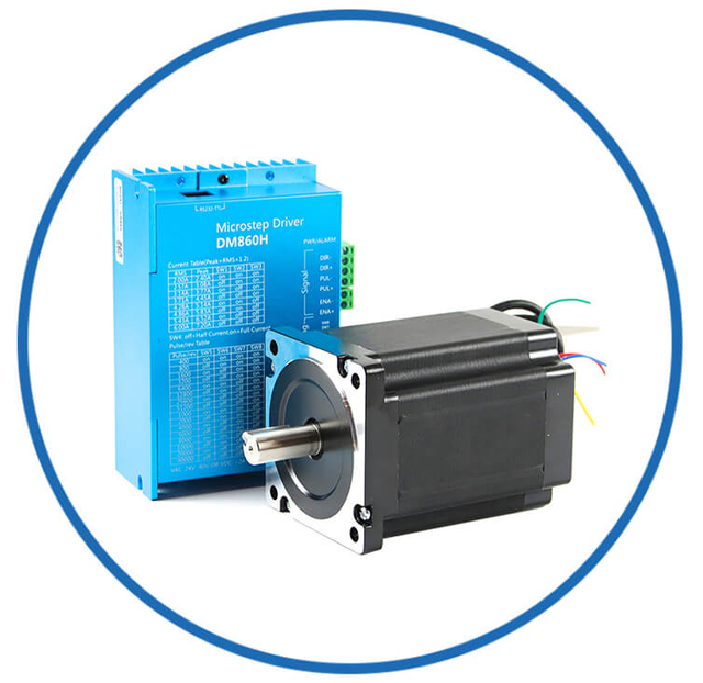
 | 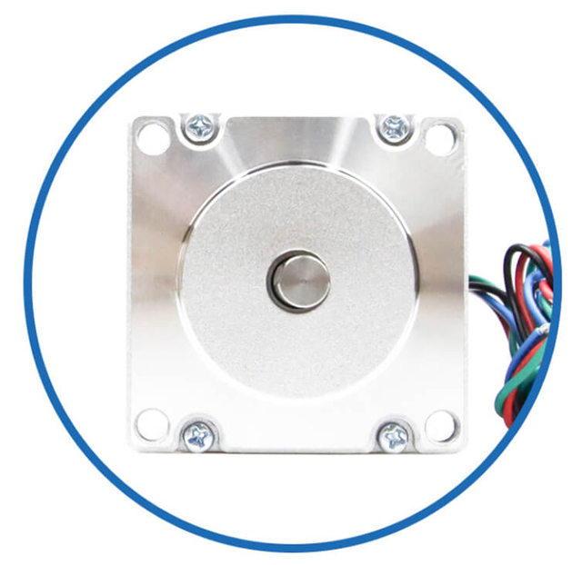 |  |  | 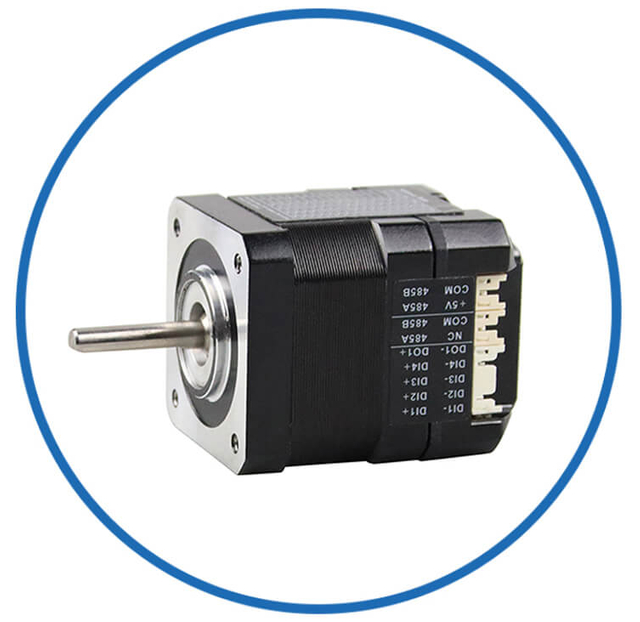 | BesFoc Customized Motors:
According to the application needs, provide a variety of customized motor solutions, common customization includes:
-
Sealed motor, suitable for dusty environment, dirty environment with small temperature change, etc
-
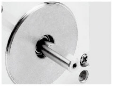
Special shaft, such as size, shape, etc
-
Belt wheels, gears and couplings etc
-
Encoders and other feedback components
-
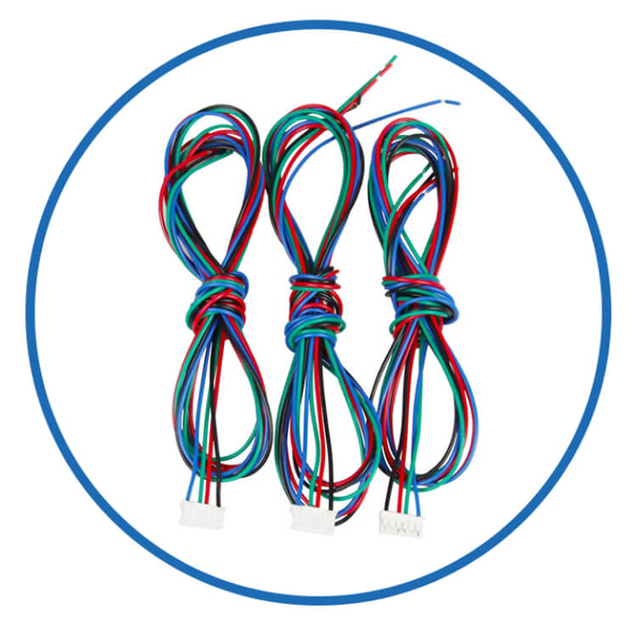
Encoders and other feedback components. Lead length and customer use termination plug-in |
WIres Cables
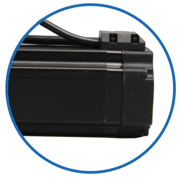
| BLDC Motor Covers
| Closed Loop System
| BLDC Motor Brakes
| Integrated Systems
|
 |  |  |  |  |
Linear Actuator
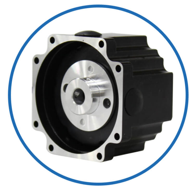
| Motor Shaft
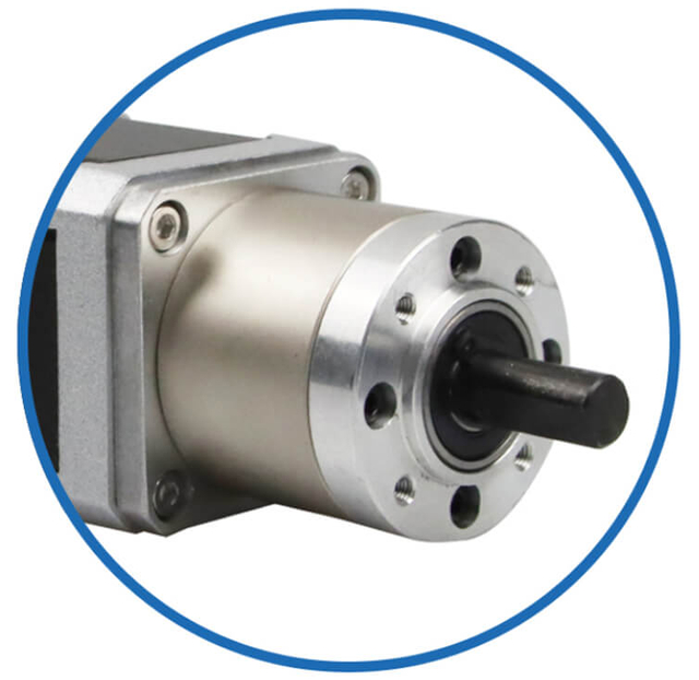
| Motor Gearbox | Driver System
| More Custom Service |
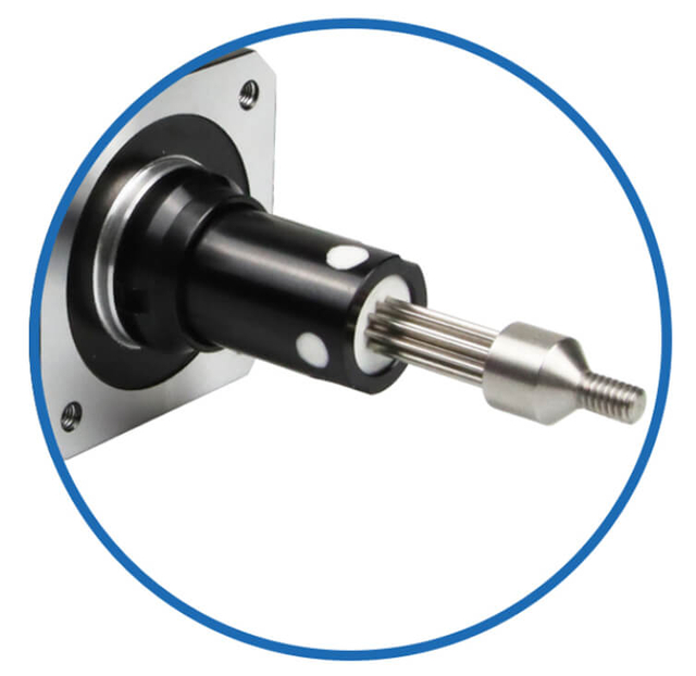
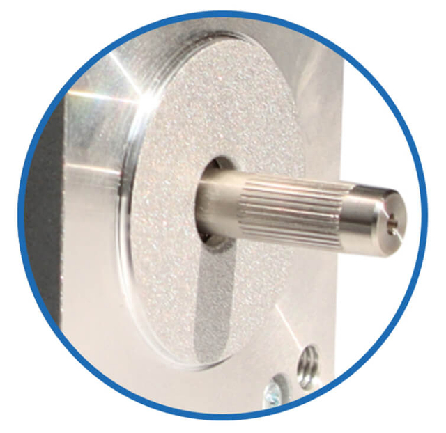
Besfoc BLDC Motor Shaft Customized Service
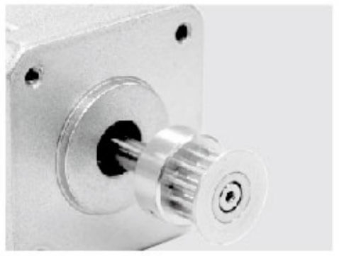 | 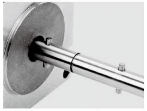 |  | 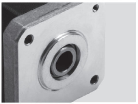 | 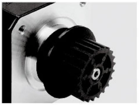 | 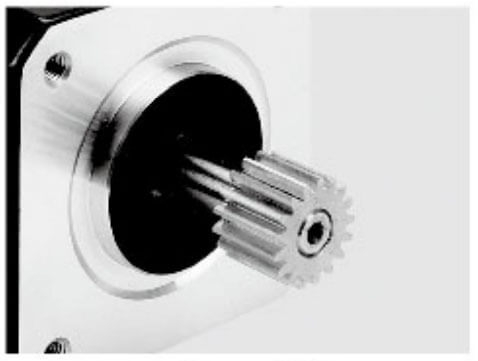 |
| Aluminum Pulley | Shaft Pin | Single D Shaft | Hollow Shaft | Plastic Pulley | Gear |
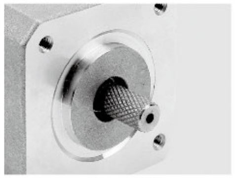 | 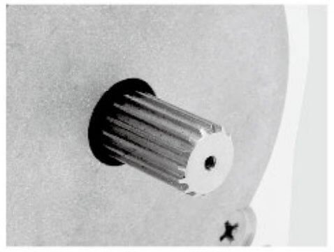 | 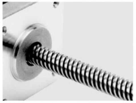 | 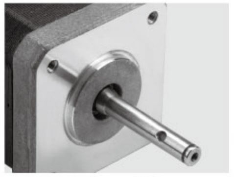 | 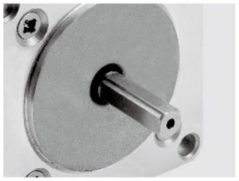 | 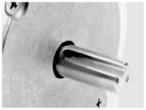 |
| Knurling | Hobbing Shaft | Screw Shaft | Hollow Shaft | Double D Shaft | Keyway |
Basic Operating Principle of BLDC Motors
A BLDC motor consists of three primary components:
Stator – The stationary part containing multiple windings.
Rotor – The rotating component equipped with permanent magnets.
Electronic Controller – The system responsible for switching current through the stator windings.
When electric current flows through the stator windings in a controlled sequence, it generates a rotating magnetic field. This magnetic field interacts with the permanent magnets on the rotor, producing torque and causing the rotor to rotate. Unlike brushed motors that use mechanical commutators, BLDC motors use electronic switching circuits to manage the timing of current flow in each winding phase.
This electronic commutation enables precise control over motor speed, torque, and direction, making BLDC motors ideal for high-performance applications such as robotics, industrial automation, drones, electric vehicles, and HVAC systems.
Key Factors Influencing BLDC Motor Speed
The speed of a BLDC motor is primarily determined by the following factors:
Supply Voltage
The applied voltage directly influences the rotational speed of the motor. Increasing the supply voltage increases the energy delivered to the windings, resulting in a higher rotational speed.
The relationship between speed and voltage is generally proportional:
Higher Voltage → Higher Motor Speed
However, the voltage must remain within the motor's rated operating range to avoid overheating or component damage.
Commutation Frequency
The controller determines the switching frequency of the stator windings, which directly controls how quickly the magnetic field rotates. The rotor follows this rotating magnetic field, meaning the commutation frequency dictates the motor speed.
Precise timing of commutation events is essential to maintain smooth and efficient rotation.
Load Conditions
Mechanical load significantly affects the motor's ability to maintain a target speed. When load torque increases, the motor requires higher current to maintain the same rotational speed. If the controller does not compensate effectively, the motor may experience speed drop or instability.
Closed-loop control systems are typically used to automatically adjust current and maintain stable operation under varying loads.
Role of Electronic Speed Controllers
The Electronic Speed Controller (ESC) is the central component responsible for regulating BLDC motor speed. It controls the timing, sequence, and magnitude of current applied to each phase of the motor windings.
Modern ESCs incorporate advanced technologies such as:
Pulse Width Modulation (PWM)
Microcontroller-based control algorithms
Feedback signal processing
Current and voltage monitoring
These systems allow for dynamic adjustment of motor behavior, enabling accurate speed regulation across a wide operating range.
Pulse Width Modulation (PWM) in Speed Control
One of the most widely used techniques for controlling BLDC motor speed is Pulse Width Modulation (PWM).
PWM works by rapidly switching the power supply on and off at a high frequency, adjusting the duty cycle to control the average voltage delivered to the motor.
PWM offers several advantages:
High efficiency
Low power loss
Precise control
Minimal heat generation
This method enables controllers to regulate speed without wasting energy in resistive elements.
BLDC motor systems typically operate using either open-loop or closed-loop control strategies.
Open-Loop Control
In open-loop systems, the controller sends predefined signals to the motor without monitoring actual motor speed. This approach is simple and cost-effective but lacks precision.
Common characteristics include:
Open-loop control is often used in fans, pumps, and simple consumer electronics.
Closed-Loop Control
Closed-loop control systems use feedback sensors to monitor the motor’s real-time operating conditions. The controller compares the actual speed with the desired speed and adjusts the control signals accordingly.
Common feedback devices include:
Hall effect sensors
Optical encoders
Resolvers
Closed-loop systems provide:
High precision speed control
Stable performance under varying loads
Improved energy efficiency
Enhanced system reliability
For demanding applications such as CNC machinery, robotics, and electric vehicles, closed-loop control is essential.
Rotor Position Detection
Accurate rotor position detection is critical for proper commutation timing. The controller must know the exact position of the rotor magnets to energize the correct stator winding phase.
Two main approaches are used:
This method uses physical sensors, typically Hall effect sensors, mounted inside the motor to detect rotor position.
Advantages include:
However, sensors increase system complexity and cost.
Sensorless control eliminates physical sensors by estimating rotor position using Back Electromotive Force (Back EMF) signals generated during motor rotation.
Benefits include:
Sensorless control is widely used in drones, electric fans, and pumps, although it can be more challenging at low speeds.
Importance of Control Algorithms
Modern BLDC systems rely on sophisticated control algorithms to achieve optimal performance. These algorithms process feedback data and dynamically adjust control signals to ensure smooth, stable, and efficient motor operation.
Popular control methods include:
Trapezoidal Control
This traditional method uses six-step commutation, energizing two phases at a time. While simple and cost-effective, it can produce torque ripple and audible noise.
Sinusoidal Control
Sinusoidal control smooths current waveforms to reduce vibration and noise. It offers improved efficiency and smoother torque output compared to trapezoidal methods.
Field-Oriented Control (FOC)
FOC is the most advanced control technique used in modern high-performance BLDC systems. It separates torque and magnetic flux control, allowing for:
Precise torque regulation
Ultra-smooth speed control
High efficiency
Excellent low-speed performance
FOC is commonly implemented in electric vehicles, robotics, and industrial servo drives.
Why Proper Speed Control Matters
Accurate BLDC motor speed control is essential for maintaining system performance, efficiency, and reliability. Poor speed regulation can lead to:
Mechanical vibration
Reduced efficiency
Increased component wear
Excessive noise
Unstable operation
By understanding the fundamental principles of voltage control, commutation timing, feedback systems, and control algorithms, engineers can design motor systems that deliver high precision, energy efficiency, and long operational life.
As industries increasingly demand smarter and more efficient motion control solutions, mastering the fundamentals of BLDC motor speed control becomes a critical step in developing next-generation electromechanical systems.
Common BLDC Motor Speed Control Problems
1. Speed Fluctuation During Operation
Speed fluctuation is one of the most common issues encountered in BLDC motor systems. The motor may accelerate or decelerate unexpectedly even when the load remains constant.
Primary Causes
Inconsistent PWM signal generation
Improper motor parameter tuning
Voltage supply instability
Low-resolution feedback sensors
When the controller fails to maintain a consistent switching pattern, the electromagnetic torque output becomes uneven, resulting in unstable speed.
Practical Solutions
Implement high-frequency PWM control to stabilize commutation timing.
Use precision Hall sensors or high-resolution encoders for accurate feedback.
Apply digital filtering techniques to eliminate signal noise.
Ensure stable DC power supply with proper voltage regulation.
In high-end systems, engineers often adopt Field-Oriented Control (FOC) to achieve extremely smooth speed regulation.
2. Poor Low-Speed Performance
Many BLDC motors struggle to maintain stable operation at very low RPM ranges. This issue is particularly critical in applications such as robotics, medical pumps, and precision positioning equipment.
Primary Causes
Back EMF signal too weak at low speeds
Inaccurate rotor position detection
Controller dead-time errors
Low torque output near zero speed
Without strong feedback signals, the controller may struggle to determine exact rotor position, resulting in hesitation or vibration.
Practical Solutions
Use sensor-based control systems instead of sensorless control.
Apply advanced startup algorithms for smooth acceleration.
Increase PWM resolution for better torque control.
Utilize FOC or vector control strategies for improved low-speed stability.
These solutions allow the motor to deliver precise torque even at extremely low rotational speeds.
3. Motor Speed Oscillation and Hunting
Speed hunting refers to a continuous oscillation around the target speed. Instead of stabilizing at the desired RPM, the motor repeatedly accelerates and decelerates.
Primary Causes
Improper PID controller tuning
Controller feedback delay
Oversensitive control loop gain
Incorrect load inertia estimation
If the PID parameters are not optimized, the controller may overcorrect speed deviations, causing repeated oscillation.
Practical Solutions
Optimize PID parameters (Proportional, Integral, Derivative gains).
Implement adaptive control algorithms.
Use high-speed microcontrollers to reduce response latency.
Add load inertia compensation in the control loop.
Modern digital motor controllers often include auto-tuning features that automatically calibrate PID parameters for optimal stability.
4. Torque Ripple Affecting Speed Stability
Torque ripple is another major contributor to speed instability in BLDC motors. It occurs due toTorque ripple** is another major contributor to speed instability in BLDC motors. It occurs due to the interaction between stator magnetic fields and rotor permanent magnets.
Torque ripple results in:
Periodic speed variation
Increased vibration
Audible noise
Reduced control accuracy
Primary Causes
Imperfect motor winding design
Uneven magnetic flux distribution
Commutation timing errors
Mechanical imbalance
Practical Solutions
Implement sinusoidal commutation or FOC control.
Optimize stator slot and winding design.
Improve rotor magnet alignment precision.
Apply advanced current shaping algorithms.
These improvements significantly reduce torque ripple and produce smoother rotational motion.
5. Electrical Noise Interfering with Control Signals
Electrical interference can corrupt sensor signals and control feedback, causing erratic speed regulation.
Common Sources
Noise contamination may cause the controller to misinterpret rotor position data, resulting in unstable commutation.
Practical Solutions
Use shielded cables for sensor connections.
Implement proper grounding architecture.
Add low-pass filters to sensor inputs.
Utilize EMI suppression components such as ferrite beads.
These measures help ensure clean and reliable control signals in high-speed motor systems.
Advanced Speed Control Technologies for BLDC Motors
As industries demand higher efficiency, greater precision, and smarter automation, traditional BLDC motor control control methods are no longer sufficient for many advanced applications. Modern systems now rely on advanced speed control technologies that combine powerful algorithms, high-speed microcontrollers, and intelligent feedback mechanisms. These technologies allow brushless DC motors to achieve smoother operation, faster dynamic response, improved energy efficiency, and superior torque stability across a wide operating range.
From industrial automation and robotics to electric vehicles and aerospace systems, advanced control strategies are essential for unlocking the full performance potential of BLDC motors.
Field-Oriented Control (FOC) for High-Precision Speed Regulation
One of the most widely adopted advanced control strategies is Field-Oriented Control (FOC), also known as vector control. FOC fundamentally transforms how BLDC motors are controlled by independently managing magnetic flux and torque components within the motor.
Unlike conventional six-step commutation, which produces stepped current waveforms, FOC generates smooth sinusoidal current patterns that align precisely with the rotor magnetic field.
Key Advantages of FOC
Ultra-smooth torque production
Extremely precise speed control
Reduced torque ripple
Improved low-speed performance
Higher overall efficiency
FOC works by converting three-phase stator currents into two orthogonal components (d-axis and q-axis) using mathematical transformations such as Clarke and Park transformations. This allows the controller to regulate torque and flux independently, providing fine control over motor behavior.
Today, FOC is widely implemented in electric vehicles, industrial servo drives, robotics, and high-end consumer appliances, where precision motion control is essential.
Sensorless Control Technology
In many modern BLDC systems, manufacturers are eliminating physical position sensors to reduce cost, simplify design, and improve reliability. Sensorless control technology estimates rotor position using electrical signals generated during motor operation.
Instead of relying on Hall sensors or encoders, the controller analyzes Back Electromotive Force (Back EMF) produced by the motor windings.
Advantages of Sensorless BLDC Control
Lower hardware cost
Reduced wiring complexity
Higher reliability in harsh environments
Improved mechanical durability
Sensorless systems are particularly useful in applications such as:
However, sensorless control requires advanced algorithms because Back EMF signals are weak or absent at low speeds. Modern controllers overcome this limitation using observer-based estimation techniques and adaptive filtering algorithms.
Adaptive PID Speed Control
Traditional PID (Proportional–Integral–Derivative) controllers have long been used for BLDC motor speed regulation. However, fixed PID parameters may not perform well under changing operating conditions.
Adaptive PID control improves performance by automatically adjusting controller parameters in real time based on system behavior.
Benefits of Adaptive PID Control
Adaptive algorithms continuously analyze feedback signals and modify gain values to maintain optimal control performance. This dynamic adjustment allows BLDC motors to maintain stable speed even under rapidly varying load conditions.
Adaptive PID control is commonly used in:
Industrial automation equipment
Smart manufacturing systems
Precision positioning devices
Space Vector Pulse Width Modulation (SVPWM)
Space Vector Pulse Width Modulation (SVPWM) is an advanced modulation technique used in modern motor drives to improve efficiency and waveform quality.
Unlike conventional PWM, which controls each phase independently, SVPWM treats the three-phase motor system as a single rotating voltage vector. By optimizing the switching states of power transistors, SVPWM produces smoother voltage waveforms and better utilization of the DC bus voltage.
Advantages of SVPWM
Higher voltage utilization (up to 15% improvement)
Reduced harmonic distortion
Lower torque ripple
Improved motor efficiency
SVPWM is frequently combined with Field-Oriented Control to create extremely efficient motor drive systems capable of delivering precise speed and torque control.
Model Predictive Control (MPC)
Another emerging technology in advanced motor control is Model Predictive Control (MPC). MPC uses a mathematical model of the motor to predict future system behavior and determine the optimal control action.
At each control cycle, the algorithm evaluates multiple possible switching states and selects the one that minimizes speed error, torque ripple, and power losses.
Key Benefits of MPC
MPC is particularly effective in applications requiring high-speed dynamic control, such as:
Electric vehicle traction systems
High-performance servo drives
Aerospace electromechanical actuators
Although computationally demanding, advances in high-speed digital signal processors (DSPs) are making MPC increasingly practical for commercial motor drives.
Artificial Intelligence and Smart Motor Control
The integration of Artificial Intelligence (AI) and machine learning algorithms is opening new possibilities in BLDC motor speed control.
AI-based motor controllers can analyze large volumes of operational data to continuously optimize motor performance. These systems learn from historical patterns and adjust control parameters automatically.
Capabilities of AI-Driven Motor Control
Real-time parameter optimization
Predictive load adaptation
Self-tuning speed control loops
Predictive maintenance diagnostics
For example, AI algorithms can detect subtle patterns in vibration, current consumption, and speed variation, allowing the system to predict potential failures before they occur.
AI-driven control is becoming increasingly important in Industry 4.0 environments, where intelligent machines must operate autonomously and efficiently.
Digital Signal Processing in Modern Motor Drives
Modern BLDC motor controllers rely heavily on Digital Signal Processors (DSPs) and high-performance microcontrollers to implement advanced control strategies.
These processors provide:
High-speed mathematical computation
Precise PWM generation
Real-time sensor data processing
Advanced communication interfaces
DSP-based controllers allow engineers to implement complex algorithms such as FOC, SVPWM, and predictive control with extremely high accuracy.
In addition, modern motor controllers often include built-in protection features, such as:
Overcurrent protection
Thermal monitoring
Voltage surge protection
Fault detection systems
These capabilities enhance system reliability and operational safety.
Integrated Smart Motor Systems
A major trend in modern motor technology is the development of integrated smart motor systems. These systems combine the motor, controller, sensors, and communication interfaces into a single compact unit.
Advantages include:
Simplified system integration
Reduced wiring complexity
Improved electromagnetic compatibility
Enhanced reliability
Smart motors can also connect directly to industrial networks such as CAN, EtherCAT, or Modbus, enabling seamless integration into automated production environments.
Future Innovations in BLDC Motor Speed Control
The next generation of BLDC motor systems will continue to benefit from rapid advancements in power electronics, semiconductor technology, and intelligent control software.
Emerging innovations include:
Gallium Nitride (GaN) and Silicon Carbide (SiC) power devices for higher switching efficiency
Digital twin technology for motor performance simulation and optimization
Cloud-connected motor monitoring systems
Edge computing for real-time motor analytics
These technologies will enable BLDC motors to achieve unprecedented levels of performance, efficiency, and reliability in increasingly complex applications.
Conclusion
Advanced speed control technologies have transformed the capabilities of modern BLDC motor systems. Techniques such as Field-Oriented Control, Sensorless Estimation, Adaptive PID Control, Space Vector PWM, and Model Predictive Control provide highly accurate speed regulation while minimizing torque ripple and energy losses.
With the integration of AI-driven algorithms, high-performance digital processors, and intelligent motor drive architectures, BLDC motors are evolving into smart, self-optimizing motion systems capable of meeting the demanding requirements of modern industries.
As technology continues to advance, these control innovations will further enhance the efficiency, precision, and versatility of BLDC motors, solidifying their role as a cornerstone of next-generation motion control solutions.
Design Considerations for Stable BLDC Motor Speed Control
Achieving reliable motor speed control requires an integrated approach that combines motor design, electronics, and control algorithms.
Key design priorities include:
High-Quality Motor Construction
Advanced Motor Controllers
High-performance DSP or microcontroller units
Fast PWM switching capabilities
High-resolution feedback processing
Reliable Power Electronics
When these elements are engineered together, BLDC motors deliver exceptionally stable and accurate speed control.
Future Trends in BLDC Motor Speed Regulation
As global industries move toward higher efficiency, intelligent automation, and electrification, the demand for more advanced BLDC motor speed regulation technologies continues to grow. Brushless DC motors are already known for their precision, reliability, and energy efficiency, but future developments in control systems, power electronics, and digital technologies are expected to further enhance their capabilities.
The next generation of BLDC motor speed regulation will be shaped by smarter control algorithms, improved semiconductor technology, integrated motor systems, and data-driven optimization. These innovations will enable motors to deliver greater performance, higher efficiency, and more adaptive operation in complex environments.
Integration of Artificial Intelligence in Motor Control
One of the most transformative trends in BLDC motor technology is the integration of Artificial Intelligence (AI) and machine learning algorithms into motor control systems. Traditional control methods rely on predefined parameters, while AI-based systems can analyze operational data and adapt in real time to changing conditions.
AI-driven motor control can improve speed regulation by:
Automatically optimizing control parameters
Predicting load variations and system disturbances
Minimizing speed fluctuations andload variations and system disturbances
Minimizing speed fluctuations and torque ripple
Improving energy efficiency through adaptive optimization
These intelligent control systems continuously learn from operating conditions such as temperature, vibration, current consumption, and load changes, allowing the motor to maintain optimal speed stability under dynamic conditions.
AI-assisted speed control is expected to become increasingly common in industrial automation, robotics, electric mobility, and smart manufacturing systems.
Adoption of Wide Bandgap Power Semiconductors
Another major trend shaping the future of BLDC motor speed regulation is the use of wide bandgap semiconductor technologies, particularly Silicon Carbide (SiC) and Gallium Nitride (GaN) devices.
Compared to traditional silicon-based components, these advanced semiconductors offer:
These advantages allow motor controllers to operate with greater efficiency and faster switching speeds, which leads to more precise PWM control and smoother motor speed regulation.
GaN and SiC devices are especially beneficial for high-performance applications, including:
As manufacturing costs decrease, these technologies are expected to become widely adopted in next-generation motor drive systems.
Edge Computing and Real-Time Motor Analytics
Future BLDC motor control systems will increasingly incorporate edge computing capabilities. Instead of sending all operational data to cloud servers, edge processors embedded within motor controllers can analyze performance data locally.
This allows for:
Real-time speed optimization
Immediate detection of control anomalies
Faster response to load changes
Improved system reliability
Edge-enabled controllers can process high-frequency motor data and instantly adjust control loops, PWM signals, and torque commands, ensuring extremely stable and responsive speed regulation.
In large industrial environments, these smart controllers can also communicate with centralized monitoring systems for coordinated machine operation.
Digital Twin Technology for Motor Optimization
Digital twin technology is emerging as a powerful tool for optimizing BLDC motor performance. A digital twin is a virtual model of a physical motor system that accurately replicates its behavior in real time.
By simulating motor operation under different conditions, engineers can:
Optimize speed control algorithms
Predict performance under varying loads
Identify efficiency improvements
Detect potential control issues before they occur
Digital twins allow manufacturers to refine motor control strategies before implementing them in real hardware, reducing development time and improving system reliability.
In the future, digital twins may continuously synchronize with real motors, enabling dynamic control optimization throughout the motor's lifecycle.
Integrated Smart Motor Systems
Another important trend is the development of fully integrated smart motor systems that combine the motor, controller, sensors, and communication modules into a single compact unit.
These integrated solutions provide several advantages:
Simplified installation and system design
Improved electromagnetic compatibility
Reduced wiring complexity
Enhanced reliability and durability
Smart motors often include built-in capabilities such as:
Self-tuning speed control algorithms
Integrated current and temperature monitoring
Automatic fault detection
Industrial communication interfaces
With these capabilities, integrated motor systems can easily connect to modern industrial networks and automation platforms.
Improved Sensor Technologies
Accurate speed regulation depends heavily on precise rotor position detection. Future BLDC motor systems will benefit from more advanced sensing technologies that provide higher resolution and improved reliability.
Emerging sensor technologies include:
High-resolution magnetic encoders
Advanced Hall-effect sensor arrays
Contactless position sensing systems
Optical and inductive encoders
These sensors enable controllers to detect rotor position with extreme precision, allowing for smoother commutation and more accurate speed control across a wider operating range.
In addition, improvements in sensorless control algorithms will further enhance performance while reducing hardware requirements.
Energy Efficiency and Sustainable Motor Control
As global energy regulations become stricter, improving motor energy efficiency will remain a key focus of BLDC motor technology development.
Future speed regulation systems will emphasize:
Minimizing switching losses
Optimizing torque output for each load condition
Reducing thermal losses in power electronics
Enhancing overall system efficiency
Advanced control strategies will dynamically adjust operating parameters to ensure the motor always runs at its most efficient speed and torque combination.
This focus on efficiency will play a critical role in reducing global energy consumption, particularly in industries where motors operate continuously.
Cloud-Connected Motor Monitoring
Another emerging trend is the integration of cloud connectivity into BLDC motor control systems. Smart controllers can transmit operational data to cloud platforms for remote monitoring and analysis.
Cloud-connected systems enable:
Remote speed performance monitoring
Predictive maintenance analysis
Centralized control of multiple motors
Data-driven optimization of motor operation
These capabilities are particularly valuable in large manufacturing facilities, smart buildings, and distributed automation systems.
Autonomous Self-Tuning Motor Drives
Future motor drives are expected to incorporate fully autonomous self-tuning capabilities. These systems automatically identify motor parameters and configure optimal control settings without manual intervention.
Self-tuning drives can:
Detect motor electrical characteristics
Adjust PID or vector control parameters
Optimize PWM switching strategies
Maintain stable speed across changing loads
This automation significantly simplifies system commissioning and ensures optimal motor performance from the moment of installation.
Summary
The future of BLDC motor speed regulation is being shaped by rapid advancements in intelligent control algorithms, high-performance power electronics, integrated motor systems, and data-driven optimization technologies.
Innovations such as AI-based control systems, wide bandgap semiconductors, digital twin modeling, edge computing, and cloud-connected monitoring will allow BLDC motors to operate with unprecedented levels of precision, efficiency, and adaptability.
As industries continue to adopt automation, electrification, and smart manufacturing, these emerging technologies will play a crucial role in enabling BLDC motors to deliver highly stable speed control and superior performance in increasingly demanding applications
Conclusion
Effective BLDC motor speed control depends on identifying the root causes of instability and implementing targeted engineering solutions. Issues such as speed fluctuation, low-speed instability, torque ripple, electrical noise, and control loop errors can all impact motor performance.
By combining precision motor design, advanced control algorithms, stable power electronics, and optimized feedback systems, engineers can achieve highly accurate and reliable speed regulation even in demanding applications.
As motion control technologies continue to evolve, BLDC motors will remain a cornerstone of high-efficiency electromechanical systems, powering everything from industrial automation to electric mobility and smart devices.

 English
 العربية
 Français
 Русский
 Español
 Português
 Deutsch
 italiano
 日本語
日本語 한국어
한국어 Nederlands
 Tiếng Việt
 ไทย
ไทย Polski
 Türkçe
 ພາສາລາວ
 ភាសាខ្មែរ
 Bahasa Melayu
 ဗမာစာ
ဗမာစာ Filipino
 Bahasa Indonesia
 magyar
 Română
 Čeština
 Монгол
 қазақ
қазақ Српски
 हिन्दी
 فارسی
فارسی Slovenčina
 Slovenščina
 Norsk
Norsk Svenska
 українська
 Ελληνικά
 Suomi
Suomi Հայերեն
 עברית
עברית Latine
 Dansk
Dansk Shqip
Shqip বাংলা
বাংলা Hrvatski
 Afrikaans
 Gaeilge
 Eesti keel
 Oʻzbekcha
 latviešu
 Azərbaycan dili
 Български
 Català


