Converting rotational motion into linear motion is one of the most essential mechanical transformations in modern engineering. From CNC machines and industrial automation to automotive systems and robotics, this conversion enables accurate, efficient, and powerful motion control. Below is a comprehensive guide that explores every major method, their working principles, advantages, drawbacks, and optimal applications.
Understanding the Fundamentals of Motion Conversion
The ability to transform rotational motion into linear motion is at the heart of countless engineering systems, from manufacturing machinery and automation platforms to medical devices and transportation technologies. To design high-performance equipment, it is essential to understand the fundamental principles that govern this conversion. Below is a comprehensive overview of how rotational energy is translated into linear displacement, the physics behind it, and the mechanical principles that make reliable and precise motion conversion possible.
What Is Motion Conversion?
Motion conversion is the process of changing energy from one type of movement to another. In most industrial and mechanical systems, the primary input is rotational motion, typically generated by electric motors, combustion engines, or manually operated shafts. Yet many tasks require straight-line, controlled linear motion.
This mismatch creates the need for mechanisms that can bridge the gap—components designed to translate torque and angular displacement into linear force and travel.
Why Convert Rotational Motion to Linear Motion?
The conversion is essential because:
Motors naturally produce rotation, but machines often require linear displacement.
Linear motion offers precise positioning, essential in robotics, CNC equipment, and automation.
Many industrial applications rely on pushing, pulling, lifting, cutting, or sliding—all requiring controlled linear movement.
In simple terms, motion conversion expands what rotational energy can accomplish.
Core Principles Behind Motion Conversion
To understand how rotational motion becomes linear, we must explore the fundamental physics that govern conversion mechanisms.
1. Angular Motion and Torque
Rotational input is defined by:
Angular velocity (ω) – how fast the shaft rotates
Angular displacement (θ) – the angle through which it turns
Torque (τ) – the rotational force applied
These parameters determine how much energy is available to perform linear work.
2. Linear Force and Displacement
Linear motion involves:
Linear velocity (v)
Linear displacement (x)
Linear force (F)
Any system that translates rotation to linear travel must convert angular energy into straight-line movement without excessive friction, backlash, or mechanical losses.
3. Mechanical Advantage
Motion conversion relies on mechanical advantage, which allows a small rotational input to create:
Mechanisms such as screws, gears, cams, and belts manipulate geometry and leverage to achieve this transformation efficiently.
How Rotational Motion Becomes Linear Motion: Fundamental Methods
While many advanced mechanisms exist, they all follow a few fundamental principles of geometric transformation. Here are the foundational conversion strategies:
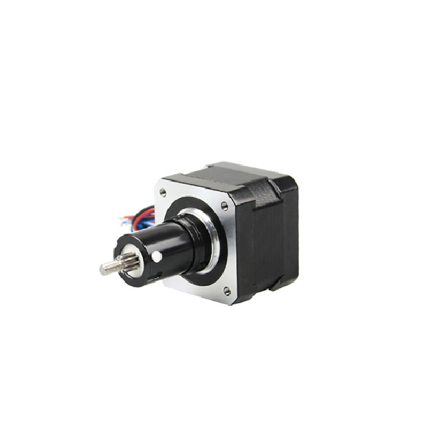
1. Helical Geometry (Lead Screws & Ball Screws)
A threaded screw converts rotation into linear movement through the helical pathway of the threads. When the screw rotates, the nut follows the thread, moving linearly.
Threads act like a continuous inclined plane
Torque is converted into straight-line travel
Precision depends on thread quality, backlash, and friction
This method provides one of the most controllable and accurate forms of motion conversion.
2. Gear Engagement (Rack and Pinion)
A circular gear (pinion) meshes with a straight gear bar (rack). As the pinion rotates, the rack moves linearly.
Rotation = circular tooth motion
Engagement with rack = linear displacement
Perfect for long travel and high force applications
The concept is simple yet extremely robust.
3. Belt and Chain Velocity Transfer
Belts and chains convert rotation to linear travel by anchoring the belt/chain to a carriage:
This method minimizes inertia and enables high-speed travel.
4. Profile Following (Cam Mechanisms)
A cam rotates and forces a follower to move along its profile:
Cam shape dictates motion pattern
Rotation produces controlled linear displacement
Ideal for repetitive, synchronized motion
Cams provide extremely predictable motion curves.
5. Sliding Linkage Geometry (Slider-Crank & Scotch Yoke)
These mechanisms convert rotary motion into reciprocating linear movement through geometric linkages:
This is the principle used in engines, compressors, and pumps.
6. Direct Electromagnetic Conversion (Linear Motors)
A linear motor produces linear motion directly without needing mechanical conversion.
Stator and mover interact electromagnetically
No contact, no friction, no wear
Motion is inherently linear
This represents the most advanced and efficient form of motion conversion.
Key Factors That Influence Motion Conversion Performance
Understanding the fundamentals isn't enough—performance depends on how well the system handles:
1. Friction and Efficiency
High friction reduces precision and increases heat and wear. Ball screws and linear motors optimize efficiency.
2. Backlash
The unintended movement between mechanical parts affects accuracy. Zero-backlash solutions include linear motors and belt drives.
3. Rigidity and Stability
Load capacity and stiffness directly impact repeatability and long-term reliability.
4. Speed and Acceleration
Applications requiring rapid travel benefit from low-inertia systems like belts and linear motors.
5. Travel Length
Long travel may require rack-and-pinion or belt systems to avoid screw whip and misalignment.
Why Motion Conversion Fundamentals Matter
A clear understanding of motion conversion fundamentals allows engineers and designers to:
Select the most suitable mechanism
Optimize precision and performance
Prevent mechanical failures
Improve system efficiency
Reduce maintenance and operating costs
Whether designing advanced automation equipment, industrial machinery, or robotic platforms, mastering these fundamentals leads to more reliable and effective engineering solutions.
Major Mechanisms for Converting Rotational Motion to Linear Motion
1. Lead Screws and Ball Screws: Precision Linear Conversion
Lead Screw Mechanism
Lead screws use a threaded shaft and a mating nut to turn rotary input into a smooth, controlled linear output. As the screw rotates, the nut travels along the threads.
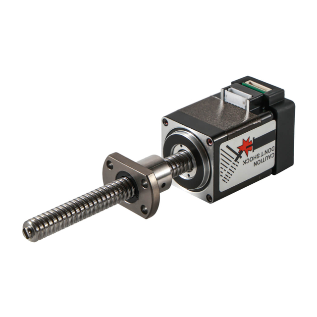
Ball Screw Mechanism
Ball screws enhance efficiency by using rolling balls inside the nut, minimizing friction and dramatically improving performance.
Key Advantages
High precision linear positioning
Exceptional repeatability
High load-carrying capability
Smooth and quiet operation
Best Applications
CNC machines
Precision stages
Medical robotics
Semiconductor equipment
Ball screws are preferred when efficiency, speed, and low backlash are critical.
2. Rack and Pinion: High-Speed, Long-Travel Linear Motion
A rack and pinion system consists of a round gear (pinion) that meshes with a straight toothed bar (rack). As the pinion rotates, it drives the rack forward or backward.
Key Advantages
Common Applications
3. Belt and Pulley Drives: Lightweight and Fast Linear Conversion
Belt-driven linear systems use a rotary servo motor connected to a timing belt. The belt is anchored to a moving carriage, and rotation creates linear displacement.
Key Advantages
Best Applications
Packaging machinery
Pick-and-place robots
Conveyor automation
Belt drives excel where speed and low inertia matter more than ultra-high precision.
4. Chain Drive Linear Actuators
Chain drive systems operate similarly to belt drives but use a metal chain for added strength.
Key Advantages
Applications
Lifting equipment
Sliding gates
Industrial conveying
5. Cam Mechanisms: Precise Profile-Based Motion
Cam systems convert rotation to linear motion by pushing a follower along a designed cam profile.
Advantages
Highly repeatable, profile-based motion
Excellent for automated machinery
Ideal for synchronized multi-axis systems
Applications
6. Scotch Yoke Mechanism: Direct Conversion with High Force Output
The Scotch yoke converts circular motion into a sinusoidal linear movement through a sliding yoke driven by a rotating pin.
Advantages
Applications
Press machines
Compressors
Pneumatic actuators
7. Slider-Crank Mechanism: Classic Rotary-to-Linear Conversion
Also known as the crankshaft system, this mechanism is one of the oldest and most widely used.
Advantages
High mechanical efficiency
Handles significant force loads
Reliable for continuous operation
Applications
8. Linear Motors: Direct Electromagnetic Conversion
Unlike mechanical systems, linear motors produce linear motion directly—without intermediate mechanical parts. A linear motor is essentially an “unrolled” rotary motor.
Key Advantages
Applications
Linear motors offer unmatched performance for advanced automation.
Choosing the Right Mechanism for Your Application
Selecting the optimal mechanism to convert rotational motion into linear motion is crucial for achieving the desired balance of performance, durability, efficiency, and precision in any engineering system. Every mechanism—whether mechanical, electromechanical, or direct electromagnetic—has unique strengths, limitations, and ideal use scenarios. Below is a comprehensive, detailed guide to help you evaluate and choose the best technology for your specific application requirements.
1. Define Your Precision Requirements
The level of precision required significantly influences your choice of mechanism. Applications like CNC machining, metrology stages, semiconductor handling, and medical robotics demand extremely accurate positioning.
Best Choices for High Precision
Ball Screws: Micron-level repeatability, low backlash, excellent efficiency.
Linear Motors: Direct electromagnetic drive with no mechanical contact, resulting in unmatched accuracy and smoothness.
Moderate Precision Needs
2. Evaluate Load and Force Requirements
Understanding the load—both dynamic and static—is essential to selecting a mechanism that can handle the forces without compromising longevity or accuracy.
High Load Applications
Ball Screws: Excellent strength and stiffness.
Rack and Pinion: Ideal for long-travel heavy loads.
Chain Drives: Perfect for rugged, high-tension jobs.
Slider-Crank and Scotch Yoke: Effective for reciprocating forces.
Low to Medium Load Applications
Belt Drives: Efficient for lightweight, high-speed systems.
Cam Mechanisms: Suitable for controlled-profile motion with consistent loads.
3. Consider Motion Speed and Acceleration
Some applications prioritize speed and rapid acceleration over extreme precision, such as packaging lines, pick-and-place robots, or high-speed conveyors.
High-Speed Options
Belt Drives: Lightweight and ideal for rapid travel.
Linear Motors: Exceptional speed and acceleration with no mechanical friction.
Rack and Pinion: Durable and capable of high linear velocity.
Moderate Speed Needs
Ball Screws: High but not as fast as belt or linear motor systems.
Lead Screws: Suitable for slower, controlled movements.
4. Determine Travel Length
Travel distance also dictates the best motion conversion mechanism. Longer travel often creates challenges related to alignment, rigidity, and maintenance.
Best for Long Travel
Rack and Pinion: Scalable to extremely long distances.
Belt Drives: Lightweight and cost-effective for long axes.
Chain Drives: Robust and durable over extended travel.
Best for Short to Medium Travel
5. Analyze Environmental Conditions
The working environment can make or break a mechanism. Dust, moisture, chemicals, temperature, and vibration all affect performance.
Harsh Environments
Chain Drives: Highly resistant to dust, grease, and industrial contaminants.
Rack and Pinion: Durable and easy to maintain.
Cam Systems: Suitable for repetitive tasks even in rugged settings.
Clean or Controlled Environments
Ball Screws: Require lubrication and protection from contamination.
Linear Motors: Sensitive to metal debris unless fully enclosed.
Lead Screws: Good for moderate conditions but need lubrication.
6. Assess Maintenance Requirements
Different mechanisms demand different levels of upkeep, depending on wear components, lubrication needs, and system complexity.
Low-Maintenance Mechanisms
Linear Motors: No contact, no wear, minimal maintenance.
Belt Drives: Simple, low-cost maintenance.
Medium to High Maintenance
Ball Screws: Require consistent lubrication and inspection.
Rack and Pinion: May need periodic lubrication depending on load and speed.
Chain Drives: Stretch over time and require tension adjustments.
7. Evaluate Cost vs. Performance
Budget plays a significant role in the selection process, but cost must be considered relative to performance needs and long-term reliability.
Cost-Effective Options
Higher Initial Investment
Ball Screws: Higher cost but superior precision.
Linear Motors: Premium performance at premium cost.
Rack and Pinion: Investment depends on length and load capacity.
Summary: Matching Mechanism to Application Needs
Here is a clear overview to simplify your selection:
| Requirement | Best Options |
| Ultra-High Precision | Linear Motors, Ball Screws |
| High Load Capacity | Ball Screws, Chain Drives, Rack & Pinion |
| Long Travel | Rack & Pinion, Belt Drives |
| High-Speed Motion | Belt Drives, Linear Motors |
| Low Maintenance | Linear Motors, Belt Drives |
| Harsh Environments | Chain Drives, Rack & Pinion |
| Cost Efficiency | Lead Screws, Belt Drives |
Selecting the right mechanism ensures superior performance, extended equipment lifespan, and optimal return on investment. By evaluating your system's specific needs across precision, load, speed, travel, environment, maintenance, and cost, you can identify the most effective solution for converting rotational motion into reliable linear motion.
Comparing Motion Conversion Technologies
| Mechanism | Precision | Speed | Load Capacity | Best For |
| Lead Screw | High | Moderate | Moderate | Precision automation |
| Ball Screw | Very High | High | High | CNC, robotics |
| Rack & Pinion | Medium | High | High | Long-travel industrial use |
| Belt Drive | Medium | Very High | Low-Medium | High-speed automation |
| Chain Drive | Low-Medium | Medium | Very High | Heavy-duty applications |
| Cam System | High | High | Medium | Profile-based motion |
| Scotch Yoke | Medium | Low | High | High force output |
| Slider-Crank | Low | Medium | High | Engines, pumps |
| Linear Motor | Very High | Very High | High | Precision manufacturing |
Conclusion: Achieving Optimal Rotational-to-Linear motion Conversion
Rotational-to-linear conversion is fundamental to modern engineering systems. Whether the goal is precision, speed, load capacity, or reliability, there is a suitable mechanism for every application. By understanding the unique characteristics of ball screws, rack and pinion systems, belt drives, cams, and linear motors, engineers can design highly efficient machines optimized for their specific performance requirements.

 English
 العربية
 Français
 Русский
 Español
 Português
 Deutsch
 italiano
 日本語
日本語 한국어
한국어 Nederlands
 Tiếng Việt
 ไทย
ไทย Polski
 Türkçe
 ພາສາລາວ
 ភាសាខ្មែរ
 Bahasa Melayu
 ဗမာစာ
ဗမာစာ Filipino
 Bahasa Indonesia
 magyar
 Română
 Čeština
 Монгол
 қазақ
қазақ Српски
 हिन्दी
 فارسی
فارسی Slovenčina
 Slovenščina
 Norsk
Norsk Svenska
 українська
 Ελληνικά
 Suomi
Suomi Հայերեն
 עברית
עברית Latine
 Dansk
Dansk Shqip
Shqip বাংলা
বাংলা Hrvatski
 Afrikaans
 Gaeilge
 Eesti keel
 Oʻzbekcha
 latviešu
 Azərbaycan dili
 Български
 Català