Determining whether a Brushless DC (BLDC) motor rotates clockwise (CW) or counterclockwise (CCW) is crucial for ensuring correct operation, alignment, and efficiency in your application. Unlike brushed motors, BLDC motors rely on electronic commutation, meaning that the motor's wiring, controller, and sensor configuration directly affect its direction of rotation. In this detailed guide, we explain how to accurately identify the rotation direction of a BLDC motor, how to reverse it safely, and why it matters for performance and longevity.
Understanding CW and CCW in BLDC Motors
In the world of Brushless DC (BLDC) motors, understanding the meaning of CW (Clockwise) and CCW (Counterclockwise) rotation is fundamental for proper installation, configuration, and operation. Whether you are working with drones, fans, pumps, or industrial automation systems, knowing how a motor's direction of rotation affects its performance can prevent mechanical misalignment, efficiency loss, or component damage. In this comprehensive guide, we will explain everything you need to know about CW and CCW rotation in BLDC motors, how to identify them, and why correct orientation is so important.
What Do CW and CCW Mean?
The terms CW (Clockwise) and CCW (Counterclockwise) refer to the direction in which the motor shaft rotates when viewed from a specific end — typically the shaft end or lead end.
CW (Clockwise Rotation): The motor shaft rotates in the same direction as the hands of a clock.
CCW (Counterclockwise Rotation): The motor shaft rotates in the opposite direction to the hands of a clock.
However, the definition depends on the viewing perspective. A motor that is CW when viewed from the shaft end will appear CCW when viewed from the lead end. For this reason, most motor datasheets and nameplates specify both the direction and the reference point, such as CWSE (Clockwise Shaft End) or CCWLE (Counterclockwise Lead End).
Why Direction of Rotation Matters in BLDC motors
The direction of rotation in a BLDC motor directly impacts mechanical performance, efficiency, and system compatibility. Choosing or wiring the wrong direction can lead to severe issues such as:
Reduced efficiency or torque output
Reversed airflow in cooling or ventilation applications
Improper thrust in drone or propeller systems
Backflow or cavitation in pumps
Misalignment in gear or conveyor systems
Correct rotation ensures that the magnetic field, sensor feedback, and load mechanics all work harmoniously for stable and efficient operation.
How BLDC Motor Rotation Works
A BLDC motor operates through electronic commutation, meaning that a controller determines when and how to energize each of the three motor windings. The sequence of electrical excitation determines the rotation direction.
This makes BLDC motors extremely flexible — you can reverse direction easily by swapping any two phase wires or by using a direction control input on the driver.
When a BLDC motor rotates clockwise (CW), the magnetic field sequence follows a specific pattern that drives the rotor in the same direction as the clock's hands.
Common uses for CW BLDC motors include:
Cooling fans and blowers that push air in a forward direction.
Drone propellers labeled as “CW” for stability and balanced torque.
Pumps and compressors that rely on CW shaft motion for proper flow.
CW rotation is often the default direction for many motors unless stated otherwise by the manufacturer.
2. CCW Rotation in BLDC Motors
In CCW (Counterclockwise) rotation, the BLDC motor's driver energizes the windings in the reverse sequence. The shaft spins opposite the direction of a clock's hands.
Typical applications for CCW rotation:
Paired drone motors that require opposite rotation for balanced thrust.
Fans or blowers designed to pull air instead of pushing it.
Mechanisms that rely on mirrored or reverse mechanical motion.
When replacing or matching motors, always confirm whether the system requires a CW or CCW model to ensure proper performance.
3. Identifying Motor Rotation: CW vs CCW
There are several reliable ways to determine whether a BLDC motor rotates CW or CCW.
a. Check the Nameplate or Datasheet
The easiest way is to read the motor label or datasheet, which typically includes:
CWSE – Clockwise viewed from Shaft End
CCWSE – Counterclockwise viewed from Shaft End
CWLE – Clockwise viewed from Lead End
CCWLE – Counterclockwise viewed from Lead End
Always note the viewing reference, as misunderstanding it can lead to reversed interpretation.
b. Observe Physical Rotation
If safe to do so, briefly run the motor and watch the shaft rotation.
Ensure the motor is not connected to a load during testing to prevent damage.
c. Check for Arrow Markings
Many BLDC motors include arrow markings on the housing or near the shaft that clearly indicate the intended rotation direction. These arrows may also be color-coded for CW and CCW versions.
4. Changing the Rotation Direction of a BLDC Motor
One of the advantages of BLDC motors is the ability to easily reverse their direction electronically.
a. For Sensorless BLDC Motors
Swap any two of the three phase wires (e.g., A ↔ B, or B ↔ C). This reverses the commutation sequence, changing CW to CCW or vice versa.
b. For Sensored BLDC Motors
If the motor includes Hall sensors, the direction depends on both phase wiring and sensor wiring. To reverse direction, you can:
Alternatively, some motor controllers have a built-in direction (DIR) pin or forward/reverse (F/R) switch. Setting this pin HIGH or LOW changes rotation direction instantly.
5. CW and CCW in Drone and Propeller Motors
In multirotor drones, motor direction is particularly critical. Drones use pairs of CW and CCW BLDC motors to balance aerodynamic torque and maintain stability.
This alternating configuration ensures that the torques cancel out, keeping the drone stable in flight. Installing a propeller with the wrong rotation direction will cause lift imbalance and possible loss of control.
6. Mechanical Clues to Identify Rotation
Even without powering the motor, you can sometimes determine its rotation based on shaft design or thread direction:
A right-hand thread on the shaft nut typically indicates CW rotation.
A left-hand thread usually corresponds to CCW rotation.
The fan blade pitch or propeller angle can also reveal the intended direction of spin.
These clues are especially useful when documentation or markings are unavailable.
7. Effects of Incorrect Rotation
Running a BLDC motor in the wrong direction can lead to several performance and safety issues:
Reversed airflow in fans or HVAC systems.
Incorrect fluid flow in pumps or compressors.
Torque imbalance in drones or multirotor systems.
Overheating due to reversed cooling fan direction.
Damage to mechanical components connected to the shaft.
Always double-check rotation direction before operating a system at full power.
8. Best Practices for Determining and Setting Motor Direction
To ensure correct operation:
Consult the datasheet or label for rotation information.
Observe the shaft end when identifying direction.
Mark the direction on your setup during installation for easy future reference.
Test the motor without load before full operation.
Use direction control pins or wiring swaps to adjust as needed.
Following these steps will help prevent costly errors and ensure smooth, efficient motor operation.
Understanding CW and CCW in BLDC motors is essential for anyone working with brushless systems — from engineers and hobbyists to manufacturers and maintenance professionals. Correctly identifying and setting the rotation direction ensures optimal performance, mechanical integrity, and safety.
Whether you determine it by the nameplate, wiring configuration, arrow markings, or visual observation, always verify direction before installation. In applications like fans, pumps, and drones, this simple step makes a significant difference in efficiency and reliability.
Check the BLDC Motor Label or Datasheet
The manufacturer's label or datasheet is the first and most reliable source of information. Most BLDC motors include one of the following markings:
CWSE – Clockwise viewed from Shaft End
CCWSE – Counterclockwise viewed from Shaft End
CWLE – Clockwise viewed from Lead End
CCWLE – Counterclockwise viewed from Lead End
These markings specify both the rotation direction and the viewing side. For example, if a motor label says “CCWSE,” it means the motor rotates counterclockwise when you look directly at the shaft.
If you're unsure which end is considered the shaft or lead side, the shaft end is typically where the load (fan, propeller, gear) attaches, while the lead end is where the wires come out.
Observe the Propeller or Fan Blade Orientation (for Drone or Cooling Motors)
In applications such as drones, fans, or pumps, the blade or propeller design indicates the required rotation direction. The blade pitch determines how air moves, so it must match the motor's rotation.
For example, drone propellers are specifically designed as CW or CCW types to balance torque and lift. Installing a CW propeller on a CCW motor (or vice versa) will severely reduce efficiency and stability.
Identify Direction by Wire Phasing
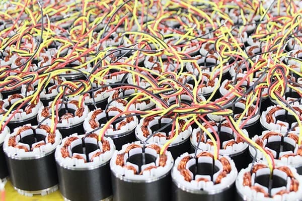
A BLDC motor typically has three power wires — often colored red, yellow, and blue — corresponding to the three stator windings. The sequence in which these windings are energized determines the direction of rotation.
Here's how it works:
The motor driver sends pulses to the windings in a specific order (e.g., A → B → C).
Reversing any two of the three wires (e.g., swap A and B) will reverse the rotation direction.
Example:
If your motor currently rotates CW, simply swap two phase wires to make it CCW.
This principle applies whether you're using sensorless or sensored BLDC systems.
⚠️ Important: Always power off the system before changing wiring connections to prevent damage to the controller or motor.
Use a BLDC Motor Driver with Direction Control Input
Many BLDC drivers include a “DIR” (Direction) or “REV/FWD” (Reverse/Forward) pin that allows easy rotation control.
Consult the driver's datasheet to verify the correct logic level. This feature is especially useful in automation, robotics, and conveyor systems, where frequent direction changes are required.
Observe the Rotation Physically
If safe to do so, you can determine rotation by briefly running the motor without a load attached. Follow these steps:
Secure the motor to prevent movement.
Connect power and the driver/controller.
Energize the motor at a low speed.
Observe the shaft or rotor movement from the shaft end.
Compare it with a clock's movement — if it spins the same way, it's CW; otherwise, CCW.
⚠️ Caution: Never run a BLDC motor without confirming that it's mechanically free and electrically connected properly. Incorrect wiring may cause immediate driver failure.
Use Hall Sensor Feedback (for Sensored BLDC Motors)
Many sensored BLDC motors include Hall-effect sensors that detect the rotor's magnetic position. The feedback sequence from these sensors determines the commutation order, which defines the rotation direction.
To verify direction:
Observe the Hall sensor output sequence (often A, B, C) with an oscilloscope or logic analyzer.
If you reverse the sensor connection order (e.g., swap Hall A and C), the rotation direction reverses.
This method is particularly useful in precision control systems, such as robotics, CNC machines, or electric vehicles, where direction accuracy is critical.
Check the Arrow Marking on the Motor Casing
Many BLDC motors have engraved or printed arrows on their casing to indicate the intended direction of rotation. These arrows are often found near:
The shaft bearing area
The motor housing side
The mounting flange
These markings are designed to help installers quickly orient the motor correctly without consulting the datasheet.
Observe the Lead Orientation and Connector Type
Some BLDC motors, especially those used in RC drones or electric scooters, come pre-wired for a specific rotation direction. Manufacturers may mark the connectors or label them as:
CW Motor (R)
CCW Motor (L)
This ensures correct propeller matching and torque balancing. Always follow the manufacturer's pairing guide when replacing or upgrading motors.
Verify with a BLDC Tester or Tachometer
If you want a precise measurement, use a digital tachometer or BLDC tester. These tools can:
Simply place the tester's sensor near the rotating shaft or attach a reflective tape for optical detection. This method provides quick, reliable verification for both small and industrial BLDC motors.
Confirm by Application Performance
Even after identifying direction, it's good practice to verify system performance. Incorrect rotation often leads to noticeable symptoms, such as:
Reduced airflow in fans or blowers
Reverse thrust in drone motors
Pump cavitation or backflow
Abnormal noise or vibration
If any of these occur, power down the motor and recheck wiring or direction configuration.
Why Correct BLDC Motor Rotation Matters
In any system that relies on a Brushless DC (BLDC) motor, ensuring that the motor rotates in the correct direction—whether clockwise (CW) or counterclockwise (CCW)—is not just a matter of preference; it’s a matter of performance, efficiency, and safety. An incorrect rotation can cause system malfunction, mechanical damage, or reduced lifespan of the entire setup. This article explores in depth why the correct BLDC motor rotation direction matters, what problems arise from incorrect rotation, and how ensuring proper alignment leads to optimal performance.
Efficiency and Performance Depend on Correct Rotation
Every BLDC motor-driven system is engineered for a specific rotation direction. The design of the fan blades, pump impellers, gearboxes, and mechanical linkages is optimized for either CW or CCW movement.
If the motor runs in the wrong direction, the system won't perform as intended. For example:
In a fan or blower, reversed rotation results in reduced airflow or even reversed air direction.
In a pump, it can cause backflow or zero suction, leading to overheating and inefficiency.
In gear-driven systems, it may generate excessive mechanical resistance, noise, or torque loss.
Thus, correct rotation ensures that the electromagnetic field aligns with the mechanical load, allowing the motor to operate at maximum efficiency and with minimal energy loss.
Mechanical Compatibility and System Alignment
Correct motor rotation is critical for mechanical synchronization with the components it drives. Many systems, such as conveyors, robotic arms, and automotive actuators, depend on precise directional movement.
If a BLDC motor rotates in the opposite direction, several issues can occur:
Misalignment of gears or shafts, leading to vibration and mechanical wear.
Unbalanced torque in dual-motor systems, causing instability.
Reverse loading on bearings, which can shorten their lifespan.
Ensuring proper CW or CCW rotation protects the mechanical integrity of the entire assembly and minimizes long-term maintenance costs.
Safety and Damage Prevention
Incorrect rotation can create serious safety hazards, especially in high-speed or high-torque applications.
Examples include:
Pumps that spin backward can build up pressure in reverse, causing seals to fail or fluid to leak.
Fans and blowers may push air in the wrong direction, affecting cooling efficiency in critical systems such as motors, generators, or HVAC units.
Electric vehicles or robots can experience unexpected movement, endangering operators or nearby components.
By confirming the correct direction before operation, engineers prevent these risks and ensure both operator safety and system reliability.
Proper Cooling and Thermal Management
Many BLDC motors use an integrated cooling fan or external airflow to maintain safe operating temperatures. These cooling systems are designed for a specific airflow direction that corresponds to the motor's rotation.
If the motor rotates incorrectly:
The cooling fan may push air away from the motor instead of drawing it through.
Heat dissipation becomes inefficient, causing overheating.
The motor's winding insulation and magnets can degrade faster, reducing lifespan.
Correct rotation ensures that the motor maintains optimal temperature and operates within its thermal limits.
Directional Functionality in Applications
Each BLDC motor-driven application relies on precise directional control for its intended purpose. A small change in rotation direction can completely alter system functionality.
a. Drones and Multirotor Aircraft
Drones use pairs of CW and CCW BLDC motors to balance torque and maintain stability.
If one motor spins in the wrong direction, the drone may lose balance or flip mid-flight.
b. Pumps and Compressors
c. Robotics and Automation
In robotic systems, incorrect rotation can cause incorrect motion sequences, collisions, or failure to reach programmed positions.
Thus, directional accuracy is essential in precision systems where control and stability are critical.
Electrical and Control System Stability
In sensored BLDC systems, the Hall sensors detect rotor position and send feedback to the controller for timing adjustments. If the motor runs in the wrong direction, the sensor sequence may become mismatched, leading to:
Erratic commutation timing
Current spikes and inefficiency
Motor stalling or vibration
Correct rotation ensures that the Hall sensor feedback aligns properly with the controller's logic, maintaining smooth and stable performance.
Reduced Wear and Extended Motor Life
Incorrect rotation can lead to abnormal mechanical stress on internal motor components. Bearings, seals, and rotor magnets are designed for specific rotational forces and load directions. Running the motor backward can result in:
By maintaining correct CW or CCW rotation, you minimize mechanical strain and extend the motor's operational lifespan.
Maintaining Manufacturer Warranty and Specifications
Most BLDC motor manufacturers specify a particular direction of rotation for warranty compliance. Operating the motor in the wrong direction, especially for extended periods, can void the warranty or breach performance conditions.
Following the manufacturer's rotation markings (CWSE, CCWSE) and wiring instructions ensures that your motor operates within its certified limits.
Energy Efficiency and Power Consumption
When a motor runs in the correct direction, the magnetic field and rotor poles interact efficiently. Incorrect rotation can cause poor commutation timing, leading to:
Higher current draw
Lower torque output
Unnecessary power loss
In energy-sensitive systems such as battery-powered vehicles or drones, this inefficiency reduces battery life and increases energy costs. Correct rotation maximizes power-to-torque efficiency and improves overall energy savings.
Easy Verification and Correction
Fortunately, verifying and correcting BLDC motor rotation is straightforward:
Check the arrow marking or nameplate for CW/CCW reference.
Observe shaft rotation briefly without a load.
Swap any two phase wires or toggle the DIR control input to reverse direction.
Taking a few seconds to confirm rotation before installation can prevent costly mechanical or electrical issues later.
The correct rotation of a BLDC motor is far more important than it might initially appear. From efficiency and mechanical alignment to safety, cooling, and system stability, every aspect of performance depends on the motor spinning in its intended direction.
Before running a BLDC motor at full speed, always confirm its CW or CCW rotation using the manufacturer's datasheet, wiring diagram, or arrow markings. Doing so ensures optimal performance, longer service life, and maximum reliability in your system.
Conclusion
Knowing how to tell if a BLDC motor is CW or CCW is a vital step in installation, testing, and maintenance. By checking the nameplate markings, wiring sequence, Hall sensor connections, or simply observing the rotation, you can easily confirm the correct direction. Always remember that reversing any two of the three phase wires will reverse the motor's direction, but verifying manufacturer markings ensures precision and safety.
A properly oriented BLDC motor not only improves performance but also extends the lifespan of both the motor and the equipment it drives.

 English
 العربية
 Français
 Русский
 Español
 Português
 Deutsch
 italiano
 日本語
日本語 한국어
한국어 Nederlands
 Tiếng Việt
 ไทย
ไทย Polski
 Türkçe
 ພາສາລາວ
 ភាសាខ្មែរ
 Bahasa Melayu
 ဗမာစာ
ဗမာစာ Filipino
 Bahasa Indonesia
 magyar
 Română
 Čeština
 Монгол
 қазақ
қазақ Српски
 हिन्दी
 فارسی
فارسی Slovenčina
 Slovenščina
 Norsk
Norsk Svenska
 українська
 Ελληνικά
 Suomi
Suomi Հայերեն
 עברית
עברית Latine
 Dansk
Dansk Shqip
Shqip বাংলা
বাংলা Hrvatski
 Afrikaans
 Gaeilge
 Eesti keel
 Oʻzbekcha
 latviešu
 Azərbaycan dili
 Български
 Català


