Home / Blog / Stepper Motor / How To Select The Right Linear Stepper Motor for Your Application ?
How To Select The Right Linear Stepper Motor for Your Application ?
Views: 0 Author: Site Editor Publish Time: 2026-04-29 Origin: Site
Selecting the optimal linear stepper motor is a decisive factor in achieving precision, reliability, and efficiency in modern motion control systems. From semiconductor equipment to medical devices and automated robotics, the correct motor choice directly impacts system performance, lifecycle cost, and scalability. We present a comprehensive, technically grounded guide to help you identify the ideal linear stepper motor for your specific application.
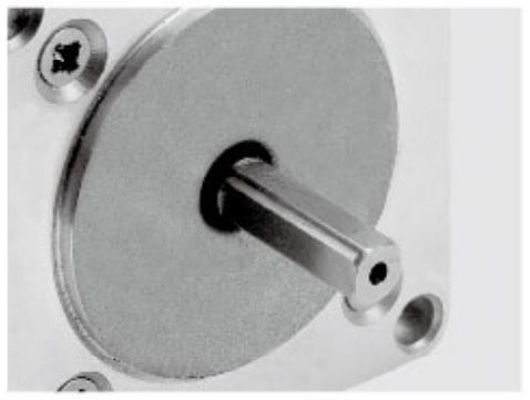
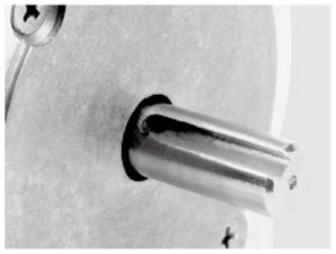
A linear stepper motor converts rotational motion into precise linear movement without requiring additional mechanical transmission components such as lead screws or belts. This direct-drive mechanism ensures:
High positioning accuracy
Repeatable motion control
Reduced mechanical complexity
Lower maintenance requirements
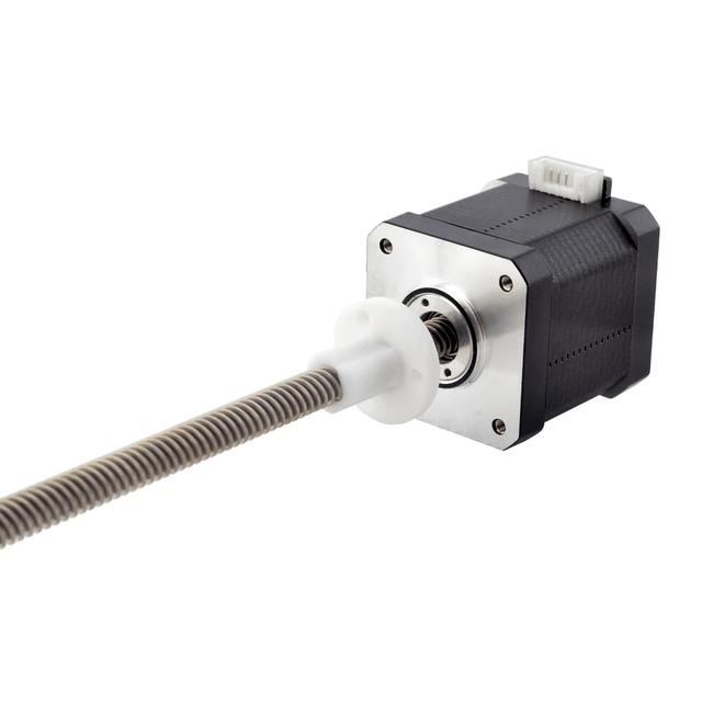
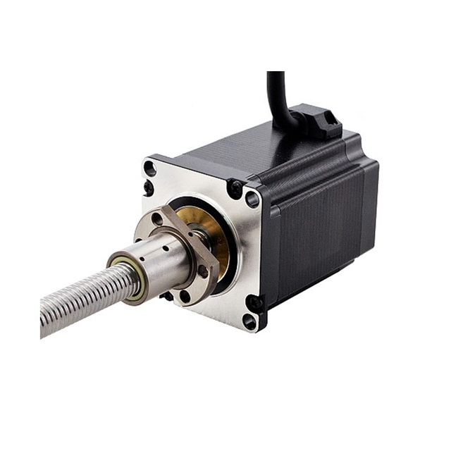
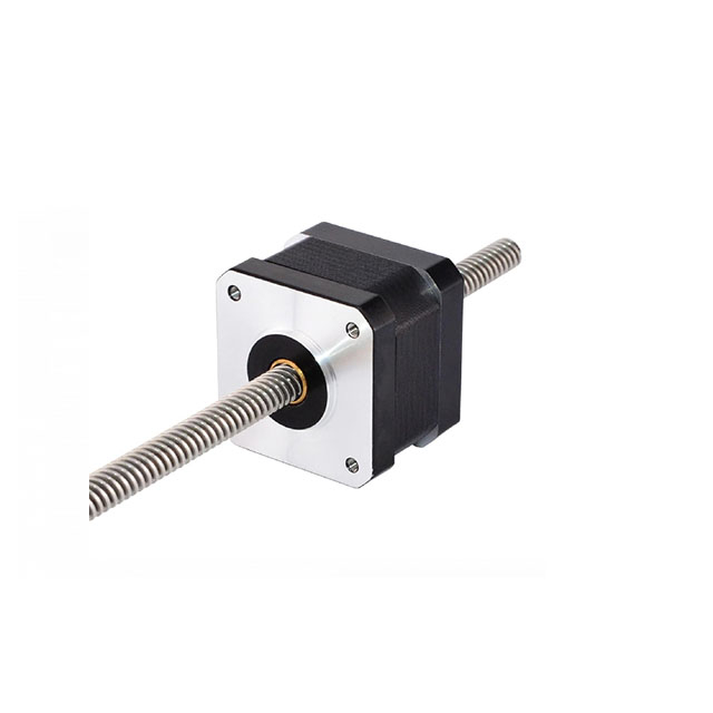
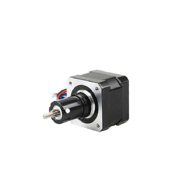
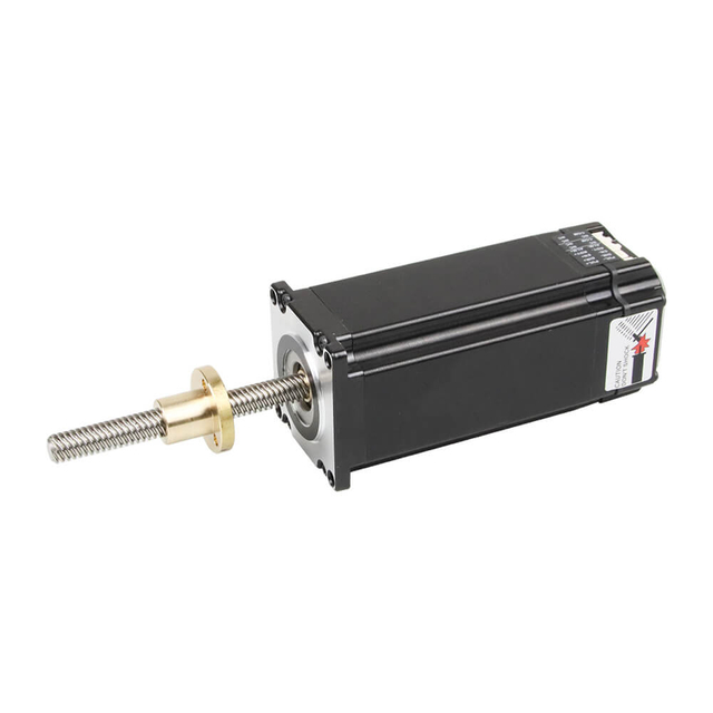
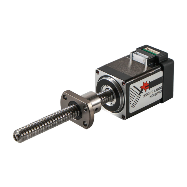
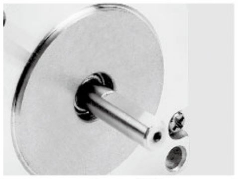
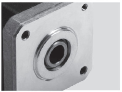
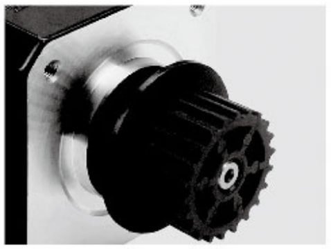
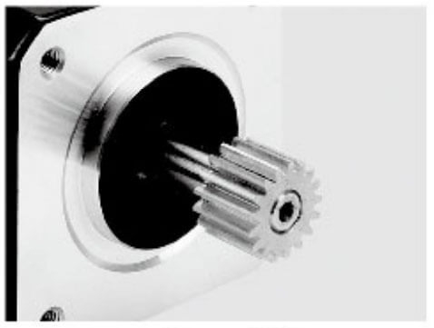
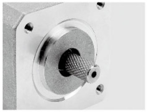
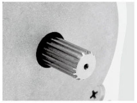
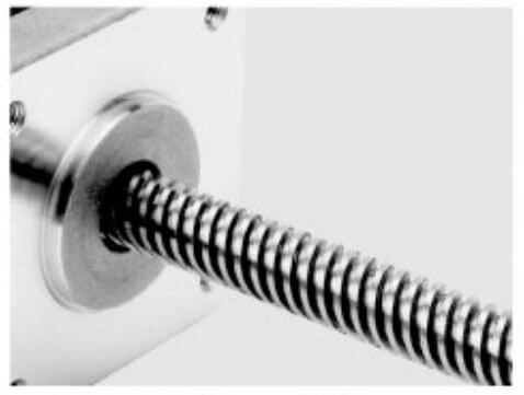
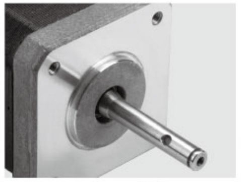
We categorize linear stepper motors into three primary types:
Selecting the right motor requires a precise analysis of performance specifications.
Thrust Force
The motor must generate sufficient linear force to move the load under all operating conditions.
Light-duty applications: < 50N
Medium-duty: 50–200N
Heavy-duty: > 200N
Always account for:
Acceleration forces
Friction losses
Safety margins
Stroke Length
Determine the total travel distance required:
Short stroke: < 50mm
Medium stroke: 50–300mm
Long stroke: > 300mm
Longer strokes often favor external nut designs for stability and efficiency.
Speed Requirements
Linear speed is influenced by:
Step angle
Lead screw pitch
Input pulse frequency
Applications like medical dosing systems require slow, ultra-precise motion, while logistics automation demands higher speeds.
Resolution and Accuracy
Precision is critical in applications such as:
Semiconductor manufacturing
Optical alignment systems
Key considerations:
Step resolution (e.g., microns per step)
Microstepping capability
Repeatability tolerance
Load Characteristics and Motion Profile
Accurately defining load characteristics and the motion profile is essential for selecting and sizing a linear stepper motor that sizing a linear stepper motor that performs reliably under real operating conditions. We translate application demands into quantifiable parameters to ensure stable motion, precise positioning, and long service life.
1. Types of Load: Static vs. Dynamic
Understanding how the load behaves over time is the foundation of correct motor sizing.
Static Load The force required to hold a position without movement. Typical in vertical axes or clamping applications. The motor must provide sufficient holding force to prevent drift.
Dynamic Load The force required during motion, including acceleration and deceleration phases. This includes:
Inertial forces (mass × acceleration)
Frictional resistance
External disturbances
We always size for the worst-case dynamic condition, not just steady-state motion.
We incorporate all resistive forces into the total thrust requirement to avoid performance degradation.
5. Motion Profile Definition
The motion profile describes how the motor moves over time. A well-defined profile ensures smooth operation and prevents mechanical stress.
Common Motion Profiles:
Trapezoidal Profile
Acceleration → Constant speed → Deceleration
Simple and widely used
Suitable for most industrial automation
S-Curve Profile
Gradual acceleration changes
Reduces vibration and mechanical shock
Ideal for high-precision or fragile systems
Step-and-Hold Motion
Incremental movement with pauses
Used in indexing and positioning applications
6. Speed and Acceleration Requirements
Speed alone is not sufficient; acceleration defines how quickly the system reaches target velocity.
Key considerations:
Maximum linear speed (mm/s)
Acceleration/deceleration rate
Cycle time requirements
High-speed applications require:
Optimized lead screw pitch
Adequate motor torque at higher step rates
Ignoring acceleration often leads to missed steps or instability.
7. Duty Cycle and Thermal Load
Duty cycle defines how frequently the motor operates within a given time frame.
Continuous Duty (100%)
Requires efficient heat dissipation
May need larger motor or cooling solutions
Intermittent Duty
Allows smaller motor sizing
Cooling periods reduce thermal stress
Thermal buildup directly affects:
Motor lifespan
Performance consistency
8. Backlash and Load Stability
Backlash can compromise positioning accuracy, especially under changing loads.
We address this with:
Anti-backlash nuts
Preloaded screw assemblies
Proper mechanical alignment
Stable load handling ensures repeatability and precision.
9. Safety Factor and Reliability Margin
We apply a safety factor (typically 1.2–1.5×) to account for:
Unexpected load variations
Wear over time
Environmental influences
This prevents borderline designs that may fail under real-world conditions.
Conclusion
A precise understanding of load characteristics and motion profile is critical for achieving optimal performance from a linear stepper motor. By carefully evaluating load type, direction, inertia, friction, and motion dynamics, we ensure the motor delivers consistent accuracy, smooth operation, and long-term reliability across demanding applications.
Environmental Conditions and Protection Requirements
Environmental factors significantly influence motor longevity and reliability.
Temperature Range
Standard: 0°C to 50°C
High-temperature applications require special insulation materials
Customization Options for Specialized Applications
In advanced motion control systems, off-the-shelf solutions are not always sufficient to meet the unique demands of specialized industries. We address these challenges through tailored linear stepper motor customization, enabling precise alignment with application-specific requirements. By optimizing mechanical, electrical, and environmental parameters, customized solutions significantly enhance performance, durability, and integration efficiency.
1. Lead Screw and Pitch Optimization
The lead screw design directly influences the motor’s speed, resolution, and thrust force. We customize:
Fine pitch lead screws for ultra-high precision and micro-positioning applications (e.g., medical dosing, optics alignment)
Coarse pitch lead screws for higher speed and longer travel per step (e.g., packaging automation)
Custom thread profiles to reduce wear and improve efficiency
This level of customization ensures the ideal balance between speed and force output.
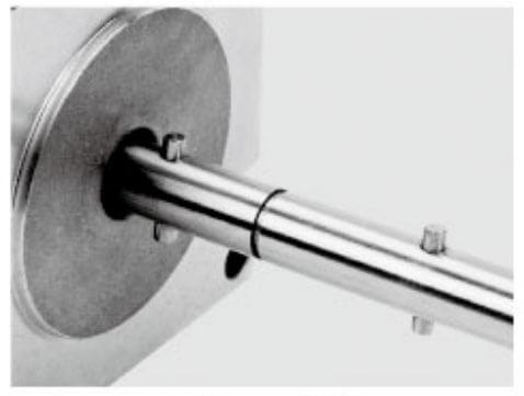
2. Stroke Length and Shaft Configuration
Different applications require different travel distances and structural designs. We offer:
Extended stroke lengths for long-range linear motion systems
Short, compact strokes for space-constrained equipment
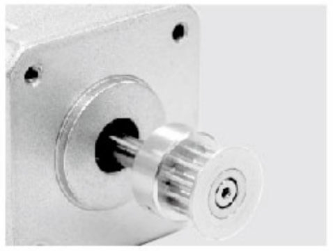
Custom shaft ends (threaded, flat, keyed) for easy coupling and integration
These modifications improve both mechanical compatibility and system flexibility.
3. Anti-Backlash and Precision Enhancements
For applications demanding high positioning accuracy, backlash must be minimized. We implement:
Anti-backlash nuts to eliminate axial play
Preloaded assemblies for consistent repeatability
High-precision machining tolerances for smoother motion
This is critical in industries such as semiconductors, medical devices, and laboratory automation.
4. Environmental Protection and Material Customization
Harsh or sensitive environments require specialized protection. We engineer motors to withstand:
Water and dust exposure (IP65/IP67 sealing) for outdoor or washdown environments
Corrosion-resistant coatings for chemical or marine applications
Vacuum-compatible materials for semiconductor and space applications
Food-grade lubricants for food processing and pharmaceutical industries
These enhancements ensure long-term reliability under extreme conditions.
5. Integrated Sensors and Feedback Systems
To improve control and monitoring, we integrate advanced sensing technologies:
Encoders for closed-loop positioning accuracy
Limit switches for travel boundary control
Hall sensors for position detection
These features enable smarter systems with real-time feedback and improved safety.
6. Electrical and Winding Customization
Electrical performance can be tailored to match specific control systems:
Custom winding configurations for optimized torque and efficiency
Voltage and current matching for compatibility with existing drivers
Low-noise designs for sensitive environments such as medical equipment
This ensures seamless integration with diverse motion control architectures.
7. Compact Integrated Designs
For applications where space and wiring complexity are critical, we provide:
These designs are ideal for robotics, portable devices, and compact automation systems.
8. Application-Specific Engineering Support
Beyond hardware, we offer engineering-level customization support, including:
Motion profile optimization
Thermal performance analysis
Lifetime and durability testing
CAD integration assistance
This ensures that every customized motor is not just a component, but a fully optimized motion solution.
Conclusion
Customized linear stepper motors provide a decisive advantage in specialized applications where standard solutions fall short. By tailoring mechanical structure, electrical performance, and environmental resilience, we enable systems to achieve higher precision, improved efficiency, and extended service life—delivering measurable value across demanding industries.
Application-Specific Selection Examples
Medical Devices
High precision and low noise
Compact captive designs preferred
Semiconductor Equipment
Ultra-clean, high-accuracy motion
Non-captive or external nut designs with vacuum compatibility
Industrial Automation
High load capacity and durability
External nut designs for long travel distances
Robotics and AGV Systems
Balance between speed and precision
Integrated solutions with compact form factors
Common Mistakes to Avoid
Selecting a linear stepper motor without a rigorous evaluation process often leads to performance issues, premature failure, or unnecessary cost escalation. We highlight the most critical mistakes that must be avoided to ensure optimal system efficiency and long-term reliability.
1. Undersizing the Motor
One of the most frequent and costly errors is choosing a motor that cannot deliver sufficient thrust force under real operating conditions.
Leads to missed steps, stalling, or inconsistent motion
Fails under peak load, not just average load
Reduces system lifespan due to constant overload
We always size the motor based on maximum dynamic load, including acceleration and friction, with an appropriate safety margin.
2. Ignoring Acceleration and Inertia
Focusing only on speed while neglecting acceleration requirements results in unstable performance.
High inertia loads require significantly more force during startup
Rapid motion profiles increase torque demand
Causes vibration, positioning errors, or complete step loss
Proper calculation of mass × acceleration (F = m·a) is essential for stable motion.
3. Incorrect Lead Screw Selection
The lead screw pitch directly affects both speed and force output, yet it is often chosen incorrectly.
Too fine pitch → high precision but insufficient speed
Too coarse pitch → high speed but reduced thrust and resolution
We ensure the lead screw is optimized for the specific balance between speed, resolution, and load.
4. Overlooking Vertical Load Requirements
Vertical applications introduce gravity as a constant opposing force.
Insufficient thrust leads to load dropping or slipping
Holding force must be maintained continuously
Requires additional safety considerations such as anti-backlash mechanisms
Ignoring gravity results in serious reliability and safety risks.
5. Neglecting Thermal Performance
Heat generation is often underestimated, especially in continuous operation.
Overheating reduces motor efficiency
Leads to insulation degradation and premature failure
Affects positioning accuracy over time
We evaluate duty cycle, ambient temperature, and cooling conditions to prevent thermal overload.
Final Selection Strategy
To ensure optimal selection, we recommend a structured approach:
Define application requirements
Calculate load and force needs
Determine stroke and speed
Evaluate environmental conditions
Match motor type and configuration
Verify control system compatibility
Consider customization if needed
Conclusion: Precision Starts with the Right Choice
Choosing the right linear stepper motor is not a trial-and-error process—it is a calculated engineering decision that directly determines system success. By aligning performance parameters, environmental considerations, and application-specific demands, we can achieve maximum efficiency, reliability, and long-term operational stability.
A well-selected linear stepper motor not only enhances performance but also reduces maintenance costs and improves overall system intelligence—making it a critical investment in advanced automation solutions.
FAQs
Q:What is a linear stepper motor and how does it work?
A: A linear stepper motor converts electrical pulses into precise linear motion without external transmission mechanisms. Besfoc motors integrate a lead screw system that enables accurate, repeatable positioning with minimal mechanical complexity.
Q: What are the main types of linear stepper motors?
A: Besfoc offers non-captive, captive, and external nut linear stepper motors. Non-captive types provide flexible shaft movement, captive designs offer guided motion, and external nut versions are ideal for long travel and higher load applications.
Q: How do I determine the required thrust force?
A: The required thrust depends on load weight, friction, acceleration, and orientation. Besfoc recommends calculating total dynamic force and adding a safety margin to ensure stable and reliable operation.
Q: How does lead screw pitch affect performance?
A: Lead screw pitch directly impacts speed and resolution. Besfoc provides fine pitches for high precision and coarse pitches for higher speed, helping users achieve the optimal balance between force and motion efficiency.
Q: What factors influence positioning accuracy?
A: Accuracy depends on step angle, microstepping capability, lead screw precision, and backlash control. Besfoc motors incorporate precision machining and optional anti-backlash designs to enhance repeatability.
Q: Which motor type is best for vertical applications?
A: For vertical motion, Besfoc recommends motors with higher thrust and anti-backlash features to counteract gravity and ensure stable holding performance without position drift.
Q: How do environmental conditions affect motor selection?
A: Environmental factors such as dust, moisture, and temperature must be considered. Besfoc offers customized solutions including IP-rated protection, corrosion-resistant materials, and cleanroom-compatible designs.
Q: Can linear stepper motors be customized?
A: Yes, Besfoc provides extensive customization options, including lead screw design, stroke length, shaft configuration, integrated sensors, and special coatings to meet unique application requirements.
Q:Do I need a closed-loop system for better performance?
A: While standard systems operate in open-loop mode, Besfoc also supports closed-loop configurations with encoders for enhanced accuracy, feedback control, and improved reliability in demanding applications.
Q: What are common mistakes when selecting a linear stepper motor?
A: Common mistakes include undersizing the motor, ignoring thermal limits, selecting the wrong lead screw pitch, and overlooking environmental conditions. Besfoc emphasizes a structured selection approach to avoid these issues.

 English
 العربية
 Français
 Русский
 Español
 Português
 Deutsch
 italiano
 日本語
日本語 한국어
한국어 Nederlands
 Tiếng Việt
 ไทย
ไทย Polski
 Türkçe
 ພາສາລາວ
 ភាសាខ្មែរ
 Bahasa Melayu
 ဗမာစာ
ဗမာစာ Filipino
 Bahasa Indonesia
 magyar
 Română
 Čeština
 Монгол
 қазақ
қазақ Српски
 हिन्दी
 فارسی
فارسی Slovenčina
 Slovenščina
 Norsk
Norsk Svenska
 українська
 Ελληνικά
 Suomi
Suomi Հայերեն
 עברית
עברית Latine
 Dansk
Dansk Shqip
Shqip বাংলা
বাংলা Hrvatski
 Afrikaans
 Gaeilge
 Eesti keel
 Oʻzbekcha
 latviešu
 Azərbaycan dili
 Български
 Català