Microstepping servo motors improve precision in optical instruments by enabling fine positioning commands, smoother low-speed movement, and closed-loop position monitoring when supported by the motion control system. These capabilities make them suitable for automated microscopes, optical inspection equipment, spectrometers, laser alignment systems, and precision lens positioning mechanisms. To achieve reliable optical positioning accuracy, engineers should consider encoder resolution, mechanical backlash, torque requirements, vibration, thermal stability, and controller tuning. By selecting the appropriate motor and validating the complete motion control assembly before mass production, manufacturers can improve positioning repeatability and support consistent performance in precision optical applications.
In this article, we examine how microstepping servo motors improve precision in optical instruments, the technical principles behind their performance, their key applications, and the factors engineers should evaluate when selecting a motor for demanding optical motion control systems.
1. What Is a Microstepping Servo Motor?
A microstepping servo motor is a motion control solution that combines fine incremental motor control with feedback-based position regulation. Depending on the design, the system may use a stepper motor with closed-loop feedback or a servo motor with a controller capable of generating fine motion commands.
The term microstepping servo motor is sometimes used broadly in the motion control industry. Therefore, engineers should distinguish between a closed-loop stepper motor with microstepping and a conventional servo motor that uses encoder feedback and advanced current control. These systems share some motion control objectives but differ in their motor construction, control methods, torque characteristics, and dynamic performance.
In a typical microstepping system, the controller divides each full motor step into smaller electrical increments. Instead of moving directly from one full-step position to the next, the motor follows a sequence of intermediate current vectors that produce smaller commanded movements.
For example, a stepper motor with a 1.8-degree full-step angle has 200 full steps per revolution. With 16 microsteps per full step, the controller generates 3,200 microstep commands per revolution.
This increases the command resolution and allows the motor to move more smoothly at low speeds.
When encoder feedback is integrated, the controller can compare the commanded position with the measured motor position and compensate for deviations within the system's operating limits.
For optical instruments, this combination is particularly useful because many positioning tasks require small, repeatable movements rather than high rotational speeds.
Typical optical motion requirements include:
Fine lens positioning for microscope focusing.
Repeatable movement of optical filters and apertures.
Controlled mirror positioning in optical alignment systems.
Precise scanning in spectrometers and imaging devices.
Stable translation of optical stages during automated inspection.
Coordinated motion of multiple axes in optical measurement equipment.
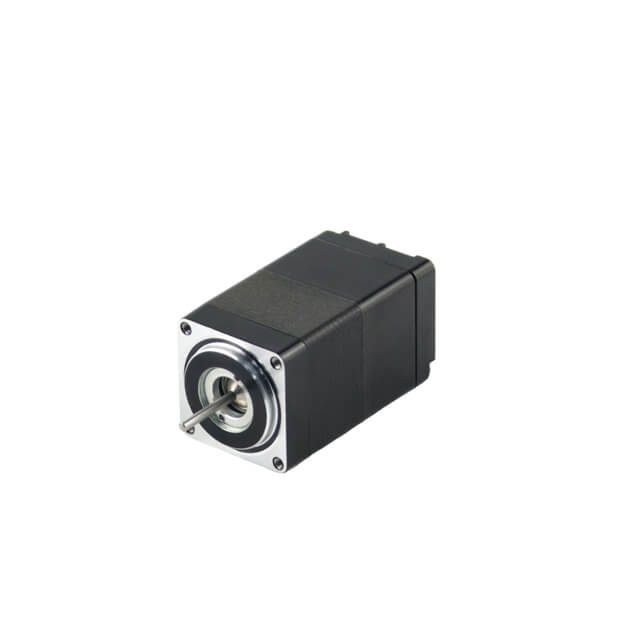
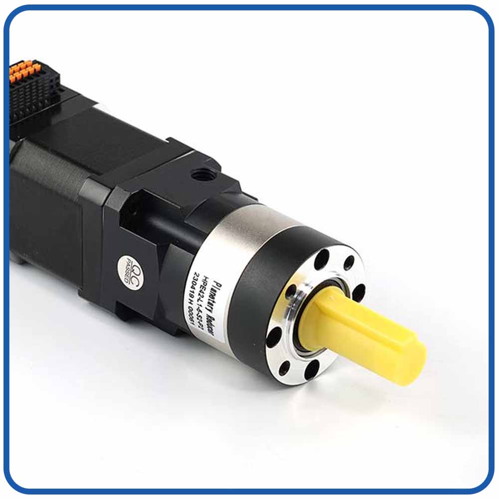
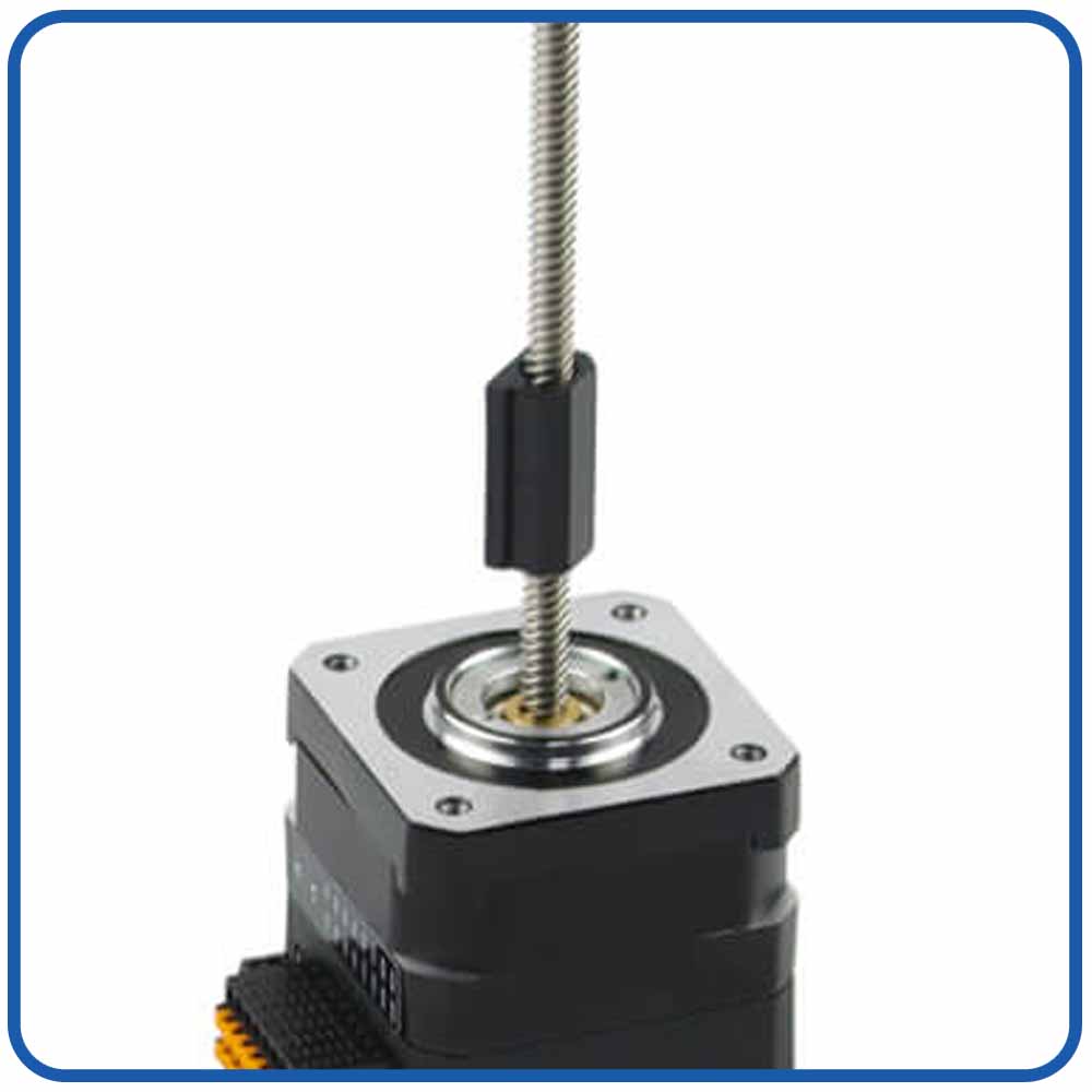
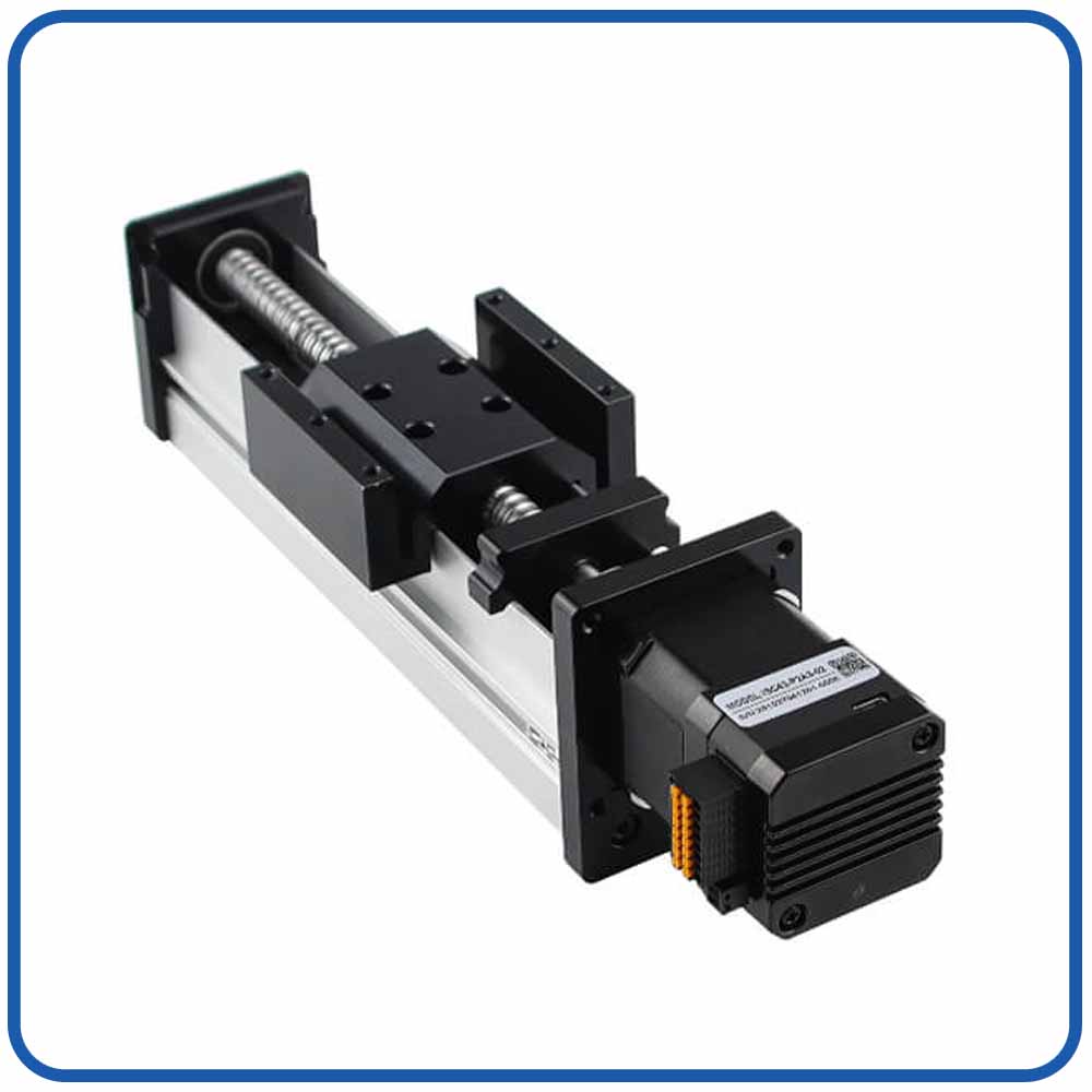
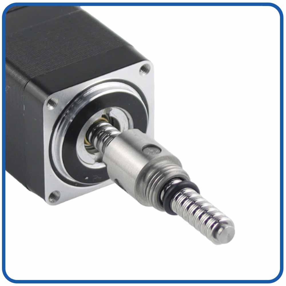
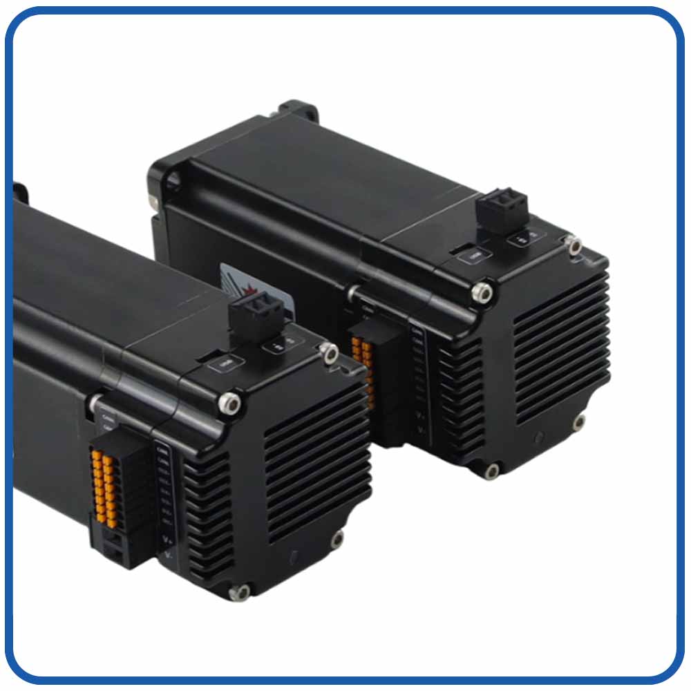
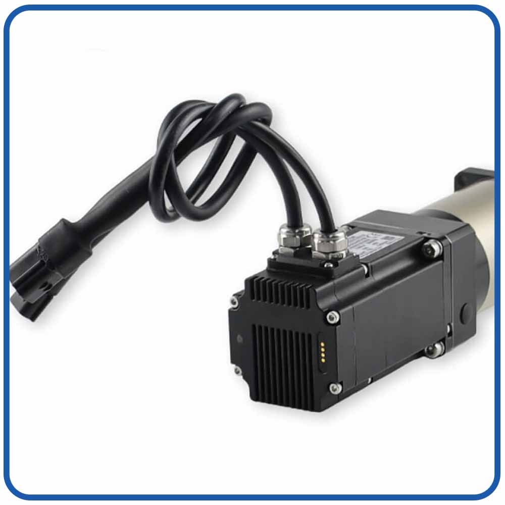
ISC28 Integrated Stepper Servo Motor — High-Efficiency, Compact, and Smart Closed-Loop Motion Control Solution
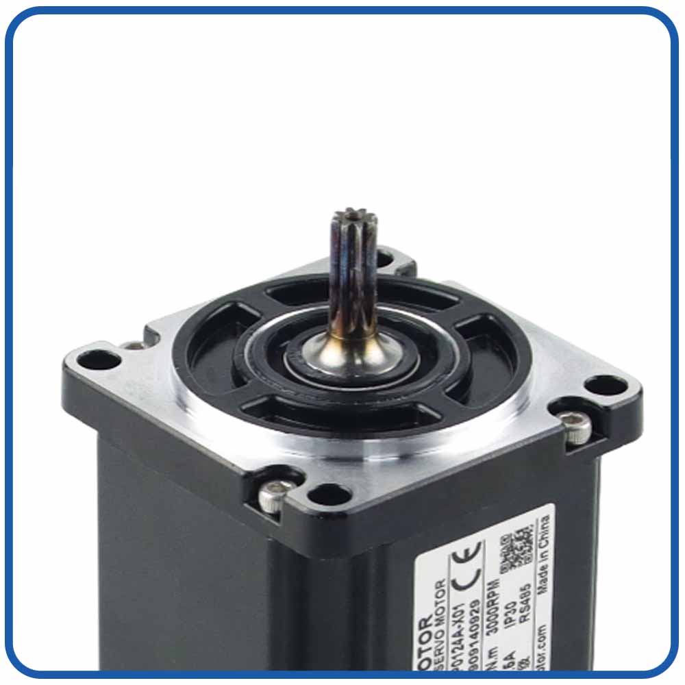
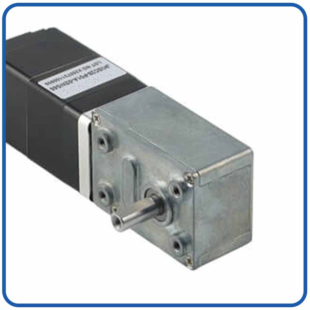
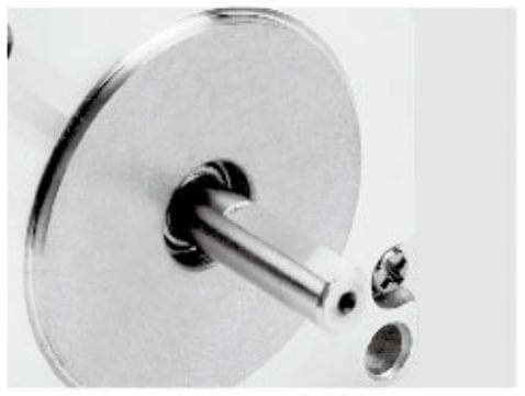
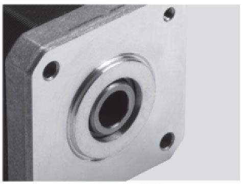
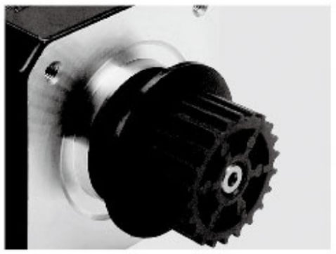
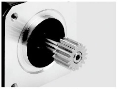
Product Overview:The NEMA 11 BFISC28-P1A3 Integrated Stepper Servo Motor combines a compact stepper motor with integrated drive and closed-loop control functionality, providing a space-saving motion solution for precision automation systems. Its compact NEMA 11 form factor makes it suitable for equipment where installation space is limited and accurate, repeatable motion is essential. By integrating key motion control components into a single unit, it helps simplify system wiring, reduce installation complexity, and support efficient machine integration. This integrated stepper servo motor is a practical choice for compact automation equipment requiring controlled positioning, reliable operation, and flexible motion control.
Key Technical Highlights
The suitability of a particular motor depends on the required positioning accuracy, load inertia, travel range, settling time, and acceptable vibration level.
Compact NEMA 11 Design: Ideal for space-constrained equipment and compact automation systems requiring a small motor footprint.
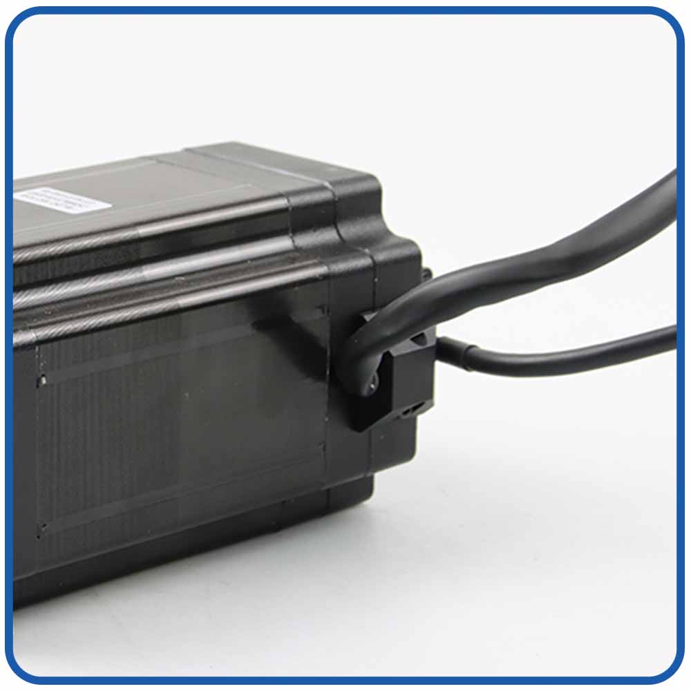
Integrated Motor and Drive: Combines essential motion control components in one assembly, helping simplify wiring and reduce installation space.
Closed-Loop Position Control: Encoder-based feedback helps monitor motor position, detect position deviations, and improve motion reliability.
Precise Positioning and Smooth Motion: Supports controlled incremental movement for applications requiring repeatable positioning and stable low-speed operation.
Simplified System Integration: Reduces component complexity and facilitates integration into automated equipment with limited installation space.
Typical Applications
Medical and Laboratory Equipment: Motorized sample handling, compact analytical instruments, and automated positioning mechanisms.
2. How Microstepping Improves Positioning Resolution in Optical Instruments
Microstepping improves positioning resolution in optical instruments by dividing each full motor step into smaller commanded increments, enabling finer control of lenses, optical stages, mirrors, and other precision components. By generating smoother incremental movements, microstepping helps optical systems perform delicate positioning tasks with greater control and reduced vibration, particularly at low speeds.
2.1 Smaller Motion Increments for Fine Optical Adjustment
Conventional stepper motors move in discrete full-step increments. Microstepping divides each full step into multiple smaller increments by regulating the motor phase currents, allowing the rotor to follow a more gradual sequence of commanded positions.
For example, a stepper motor with a 1.8° full-step angle provides 200 full steps per revolution. When configured for 16 microsteps per full step, it supports 3,200 commanded increments per revolution, reducing the nominal angular command increment from 1.8° to 0.1125°.
This finer command resolution is valuable in optical instruments that require small, controlled movements, including microscope focusing mechanisms, precision lens positioning systems, and automated optical inspection stages.
2.2 Higher Linear Resolution in Motorized Optical Stages
When a microstepping motor drives a lead screw or precision translation stage, its rotational movement is converted into linear displacement. Increasing the microstepping ratio reduces the nominal linear displacement associated with each command.
For example, with a 2 mm lead screw and a motor providing 200 full steps per revolution, the nominal linear travel per full step is 10 μm. At 16 microsteps per full step, the theoretical command increment becomes 0.625 μm.
This finer command granularity allows engineers to specify smaller movements when adjusting optical components or scanning samples. However, theoretical command resolution does not equal actual positioning accuracy. Backlash, friction, screw lead error, structural deformation, and encoder resolution can limit the achievable precision.
2.3 Smoother Motion and Reduced Vibration
Microstepping gradually changes the motor's phase currents, reducing the abrupt torque transitions associated with conventional full-step operation. This can improve low-speed motion smoothness and reduce vibration transmitted to sensitive optical components.
In high-magnification microscopes, laser alignment systems, and precision optical measurement equipment, reduced vibration can help minimize disturbances during positioning and improve stability before measurements begin.
Actual vibration performance depends on motor design, drive-current regulation, mechanical resonance, load inertia, and controller tuning. Microstepping should therefore be combined with appropriate mechanical design and optimized motion profiles.
For applications requiring reliable positioning, microstepping can be combined with encoder feedback. The controller compares the commanded position with the measured motor position and responds to detected deviations according to its control strategy.
This combination can help identify lost steps, compensate for certain load disturbances, and improve motion consistency within the system's operating limits.
For demanding optical applications, engineers should also distinguish between motor-shaft accuracy and actual optical-stage accuracy. A motor-mounted encoder measures the motor position, while a linear encoder mounted on the stage can measure output displacement more directly and help address certain transmission-related errors.
In summary, microstepping improves positioning resolution by enabling smaller commanded movements, smoother motion, and finer control of optical components. When combined with suitable feedback, precision mechanics, and careful controller tuning, it provides an effective motion control solution for optical instruments that require repeatable and finely controlled positioning.
3. Reduced Vibration and Improved Motion Smoothness
Vibration is a significant concern in precision optical instruments. Mechanical disturbances can affect image sharpness, measurement stability, laser alignment, and the repeatability of optical scans.
Conventional full-step operation can generate noticeable torque pulsations because the motor moves between discrete equilibrium positions. These disturbances may excite mechanical resonances in the motor, coupling, transmission, or optical stage.
Microstepping helps reduce these effects by dividing the electrical excitation into smaller increments.
3.1 Smoother Low-Speed Motion
During microstepping operation, the controller gradually adjusts the phase currents to create a rotating magnetic field. The motor rotor follows the changing magnetic equilibrium position rather than moving only between full-step positions.
This generally produces smoother low-speed movement and can reduce the vibration associated with full-step transitions.
For optical instruments, smoother motion is valuable when a lens or stage must move slowly while maintaining consistent mechanical behavior.
Applications include:
Fine focusing in digital microscopes.
Slow scanning in optical measurement systems.
Controlled movement of lens assemblies.
Precision translation in machine vision equipment.
Positioning of optical components during calibration.
Nevertheless, microstepping does not eliminate vibration. The actual result depends on the motor's electromagnetic design, current regulation, load inertia, mounting stiffness, and mechanical resonance.
3.2 Improved Stability During Fine Adjustment
In a precision optical system, motion quality matters even after the motor reaches its target position. Mechanical oscillation can delay image capture or introduce uncertainty into measurements.
A properly configured closed-loop controller can monitor position error and adjust motor current to improve tracking and settling behavior.
Some integrated closed-loop stepper systems also provide stall detection or position-error monitoring, depending on their controller and feedback architecture.
These functions help engineers identify abnormal operating conditions and maintain more consistent motion.
For applications requiring extremely low vibration, such as interferometry or high-magnification imaging, additional measures may be necessary. These can include mechanical isolation, optimized acceleration profiles, rigid mounting structures, and dedicated vibration-damping components.
4. Closed-Loop Feedback Helps Maintain Position Accuracy
Microstepping improves command granularity, but feedback is essential when the application requires the controller to monitor actual motor movement.
In a closed-loop motion control system, an encoder measures motor position and sends feedback to the controller. The controller compares the measured position with the commanded position and calculates the position error.
Based on the motor and drive architecture, the controller may adjust current, velocity, or other control parameters to reduce that error.
4.1 Position Error Detection and Correction
Optical instruments may experience changes in mechanical resistance, load, or operating conditions. Without feedback, a stepper motor can lose synchronization with its commanded position if the available torque is insufficient.
A closed-loop stepper motor can detect certain deviations between commanded and measured motor position. Depending on the controller, it may compensate for the error or trigger an alarm when the error exceeds a configured threshold.
A servo motor system typically uses feedback as a core part of its position-control loop, allowing it to regulate motion dynamically.
For optical positioning applications, this can improve confidence in repeatability and reduce the risk of undetected motor-position errors.
However, motor-mounted encoder feedback does not automatically guarantee that the optical component itself is positioned accurately. Backlash, coupling compliance, screw errors, and thermal expansion may cause the output stage to deviate from the motor's measured position.
When output accuracy is critical, engineers may need a linear encoder or another feedback device mounted directly on the optical stage.
4.2 Encoder Resolution and System Accuracy
Encoder resolution determines how finely the feedback system can distinguish motor movement. Higher resolution can improve position measurement granularity, but it does not independently determine absolute positioning accuracy.
Engineers should consider the following factors:
Encoder resolution and measurement accuracy.
Controller sampling rate and control-loop bandwidth.
Motor torque and dynamic response.
Mechanical transmission errors.
Load inertia and external disturbances.
Output-stage feedback requirements.
For example, an optical translation stage driven by a motor with a high-resolution encoder may still exhibit positioning errors if the lead screw has significant backlash or the stage experiences thermal drift.
For demanding applications, the complete feedback architecture should be selected according to the required output accuracy and repeatability.
5. Better Repeatability in Automated Optical Measurement
Repeatability describes a system's ability to return to the same position under consistent operating conditions. It is particularly important in automated optical instruments that repeatedly inspect samples, capture images, or perform dimensional measurements.
Microstepping servo motors can support repeatable motion by providing fine position commands and, where closed-loop control is available, monitoring movement against those commands.
5.1 Consistent Focusing and Scanning
Automated microscopes often move objective lenses or specimen stages between predefined positions. Optical inspection equipment may need to scan multiple measurement points in a fixed sequence.
In these applications, repeatable positioning helps ensure that the optical system returns to the intended measurement location.
Microstepping supports fine movement increments, while feedback-based control can reduce the risk of accumulated motor-position errors.
For example, a machine vision system may move a sample stage through a series of inspection coordinates. A suitable closed-loop motor system can help execute the motion sequence consistently, provided the stage mechanics and feedback configuration support the required precision.
5.2 Repeatability Across Repeated Operating Cycles
Optical equipment used in laboratories and automated manufacturing may operate through thousands of motion cycles.
Over time, variations in friction, temperature, load, and mechanical wear can influence motion performance.
A closed-loop controller can identify certain changes in motor-position error and compensate within its control limits. This can improve consistency compared with an open-loop system under changing loads.
However, feedback cannot eliminate every source of repeatability error. Mechanical backlash, loose couplings, guideway wear, and temperature-dependent dimensional changes must still be addressed through proper system design and maintenance.
For optical applications with demanding repeatability requirements, engineers should test the complete mechanism under representative operating conditions.
6. Faster Settling and More Efficient Motion Control
Settling time is the time required for a positioning system to reach its target and remain within a specified error band.
In automated optical instruments, excessive settling time reduces throughput because the system must wait for movement and vibration to stabilize before capturing an image or taking a measurement.
Microstepping can improve motion smoothness during low-speed movement, while a properly tuned closed-loop controller can help manage acceleration, deceleration, and final positioning.
6.1 Optimized Acceleration and Deceleration
Sudden changes in velocity can excite mechanical resonance, particularly in lightweight optical stages and structures with limited stiffness.
Motion controllers can reduce these disturbances by using controlled acceleration and deceleration profiles. S-curve profiles, for example, limit abrupt changes in acceleration and may reduce mechanical excitation in suitable systems.
When combined with an appropriately selected motor, these profiles help balance positioning speed and stability.
6.2 Balancing Speed and Precision
Higher microstepping ratios do not necessarily make a system faster or more accurate. They increase the number of available command increments, but actual performance depends on motor torque, drive current, controller bandwidth, mechanical resonance, and load conditions.
For this reason, engineers should optimize the motion profile according to the application's priorities.
A microscope focusing mechanism may prioritize smooth, low-speed movement. An automated optical inspection stage may require both rapid travel and precise final positioning. A laser alignment mechanism may place greater emphasis on low vibration and stable output positioning.
Selecting the correct combination of motor, drive, feedback device, and motion profile is essential for achieving the desired balance.
7. Applications of Microstepping Servo Motors in Optical Instruments
Microstepping servo motors and related closed-loop motion control solutions can be used in a wide range of optical systems.
7.1 Automated Microscopes
Motorized focusing mechanisms and specimen stages require controlled movement to support image acquisition at different focal planes. Fine motion commands can improve focus adjustment, while closed-loop feedback can help maintain consistent positioning across repeated imaging cycles.
7.2 Optical Inspection Equipment
Automated inspection systems move samples, lenses, and cameras between predefined measurement locations. Repeatable positioning helps maintain consistent inspection conditions and supports reliable image-based measurements.
7.3 Spectrometers and Optical Scanning Systems
Spectrometers may require controlled movement of gratings, slits, filters, or other wavelength-selection components. Fine motion control can support repeatable scanning and adjustment, subject to the optical mechanism's resolution and calibration requirements.
7.4 Laser Alignment and Beam Positioning
Precision motorized stages and optical mounts can use fine motion commands to adjust component positions during setup, calibration, or automated alignment. The required control architecture depends on whether the system moves a translation stage, a rotary mount, or a fast optical steering element.
7.5 Lens Manufacturing and Testing
Lens inspection and assembly equipment may require precise adjustment of lens holders, focusing assemblies, and measurement stages. Closed-loop motion control can support repeatable movement during testing, positioning, and calibration procedures.
These applications share a common requirement: the motor must deliver predictable motion without introducing unacceptable vibration, positioning error, or mechanical disturbance into the optical system.
8. How to Select a Microstepping Servo Motor for Optical Instruments
Choosing a suitable motor requires evaluating the complete motion control system rather than focusing exclusively on microstepping resolution.
8.1 Define the Required Positioning Accuracy
Start by determining the actual output accuracy required by the optical instrument.
Engineers should distinguish between:
Command resolution: The smallest position increment that can be commanded.
Positioning accuracy: How closely the system reaches the requested position.
Repeatability: How consistently the system returns to the same position.
Settling time: How quickly the system reaches and maintains the required position tolerance.
These specifications describe different aspects of performance and should not be used interchangeably.
For example, a system with submicrometer command increments may not achieve submicrometer positioning accuracy if its transmission mechanism has significant backlash or lead error.
8.2 Evaluate Torque and Load Inertia
The motor must provide sufficient torque to accelerate the load, overcome friction, and maintain the required motion profile.
For optical stages, the load may include the stage itself, a specimen holder, lenses, filters, or additional mounting hardware.
Engineers should evaluate both holding requirements and dynamic torque requirements at the intended operating speed. Excessive load inertia can increase settling time and excite mechanical resonance.
An appropriately sized motor helps maintain stable operation without unnecessary mass, power consumption, or heat generation.
8.3 Select the Appropriate Feedback Device
Encoder selection should match the positioning requirements and control architecture.
A motor-mounted encoder measures motor position, which can be sufficient for many applications. A linear encoder mounted on the optical stage can provide direct output-position feedback and help compensate for certain transmission errors.
The choice depends on whether the application requires motor-shaft positioning, accurate linear displacement, or direct control of the optical component.
8.4 Consider Vibration, Noise, and Thermal Stability
Optical systems can be sensitive to vibration and temperature changes.
Motor current, drive tuning, mounting stiffness, acceleration profiles, and mechanical isolation all influence vibration. Heat generated by the motor and drive can also affect nearby optical components or cause dimensional drift in the supporting structure.
Where thermal stability is critical, engineers should assess heat dissipation, duty cycle, motor placement, and temperature changes throughout the operating cycle.
8.5 Check Integration and Communication Requirements
Integrated motion control products combine the motor with selected drive and control electronics in a single assembly. Depending on the model, they may offer encoder feedback, configurable control modes, and communication interfaces.
Integration can reduce cabinet space, simplify wiring, and shorten installation time.
Before selecting an integrated microstepping servo motor, engineers should verify:
Supply voltage and current requirements.
Continuous and peak torque ratings.
Encoder specifications.
Supported control modes.
Pulse, analog, or network communication options.
Alarm and fault-monitoring functions.
Physical dimensions and mounting compatibility.
Thermal performance and environmental protection.
The selected interface must be compatible with the optical instrument's controller and automation architecture.
9. Microstepping Servo Motors vs. Open-Loop Stepper Motors
Both microstepping servo motors and open-loop stepper motors can provide fine motion commands. The primary difference is whether the system uses feedback to monitor actual movement and respond to position errors.
Performance factor
Open-loop stepper motor
Microstepping with closed-loop feedback
Motion commands
Supports full-step and microstep commands, depending on the drive
Supports fine motion commands with feedback-based position monitoring
Position feedback
Not inherently required
Uses feedback when equipped with an encoder or other position sensor
Lost-step detection
Generally unavailable without additional sensing
Possible when the controller monitors position error
Load variation
Performance depends on available torque and operating conditions
Can compensate for certain disturbances within control limits
Low-speed smoothness
Can be improved with microstepping
Depends on microstepping, feedback, drive tuning, and motor design
System complexity
Often simpler
Requires compatible feedback hardware and control
Optical applications
Suitable for cost-sensitive positioning tasks with adequate accuracy margins
Suitable for applications that benefit from monitored positioning and improved error management
A closed-loop microstepping system is not automatically superior in every application. An open-loop stepper motor may be adequate when loads are predictable and the required positioning tolerance is achievable with sufficient margin.
A closed-loop solution becomes more attractive when position errors must be detected, loads vary, or repeatable motion is important to the instrument's operation.
For applications requiring particularly high dynamic performance, engineers should also compare conventional servo motors with closed-loop stepper systems. The best choice depends on torque-speed characteristics, inertia, bandwidth, thermal behavior, and the complete positioning requirement.
10. Common Design Challenges and How to Address Them
Microstepping servo motors can improve positioning precision in optical instruments, but several factors may affect their performance.
10.1 Mechanical Backlash
Backlash in lead screws, gears, or couplings can cause positioning errors, especially when the motor changes direction. Use low-backlash transmission components and consider direct stage feedback when higher accuracy is required.
10.2 Vibration and Resonance
Mechanical resonance can affect optical alignment and measurement stability. Optimize motor mounting, acceleration profiles, and controller settings to reduce vibration and improve settling time.
10.3 Thermal Drift
Motor heat and ambient temperature changes can cause dimensional expansion, affecting optical positioning accuracy. Ensure proper thermal management and use temperature-stable mechanical components where necessary.
10.4 Incorrect Microstepping Settings
A higher microstepping ratio does not automatically guarantee higher positioning accuracy. Select an appropriate ratio based on required resolution, available torque, load conditions, and controller performance.
10.5 Insufficient System Testing
Motor specifications alone cannot guarantee optical system accuracy. Test positioning accuracy, repeatability, vibration, settling time, and thermal stability under actual operating conditions before mass production.
11. How to Test Microstepping Servo Motors Before Mass Production
Testing before mass production is essential for confirming that the selected motor performs reliably in the intended optical instrument. A structured validation process can identify positioning errors, vibration problems, thermal limitations, and integration issues before they affect production quality.
11.1 Verify Positioning Resolution and Accuracy
Command a sequence of small movements across the intended travel range and measure the actual output displacement using an appropriate instrument, such as a calibrated linear encoder, displacement sensor, or interferometric measurement system.
Compare commanded positions with measured positions to determine whether the mechanism meets the required accuracy and resolution.
11.2 Measure Repeatability
Move the optical stage to the same target position repeatedly under consistent conditions. Record the measured position after each movement and calculate the variation across repeated cycles.
Test both unidirectional and bidirectional positioning when direction reversal is part of normal operation. This helps identify repeatability limitations and possible backlash.
11.3 Evaluate Vibration and Settling Time
Use a suitable displacement sensor, accelerometer, or other measurement instrument to evaluate motion disturbances during movement and after the motor reaches its target.
Determine how long the system takes to settle within the specified position tolerance. Repeat the test using representative acceleration profiles and payloads.
11.4 Test Thermal Performance
Operate the motor through representative duty cycles while monitoring motor temperature and, where relevant, the temperature of nearby optical components and mechanical structures.
Check whether thermal changes produce unacceptable position drift, reduced torque, or controller faults.
11.5 Validate Feedback and Fault Handling
Test encoder feedback, position-error monitoring, alarms, and recovery procedures where these functions are supported.
Introduce controlled variations in load or operating conditions to verify that the controller responds as expected. Testing should remain within the manufacturer's permitted operating limits.
11.6 Confirm Communication and System Integration
Verify the motor's communication interface, command timing, parameter configuration, and coordination with the main instrument controller.
Run complete operating sequences to confirm that motion commands, feedback data, and fault signals behave correctly under realistic operating conditions.
Completing these tests before mass production helps reduce integration risks and provides measurable evidence that the motor and mechanical assembly meet the instrument's requirements.
FAQ:
FAQ 1: How do microstepping servo motors improve precision in optical instruments?
Microstepping servo motors improve optical positioning by enabling fine motion commands, smoother movement, and feedback-based position monitoring when equipped with a suitable closed-loop control system. These features help control the movement of lenses, optical stages, mirrors, and other components that require repeatable positioning.
FAQ 2: What is microstepping technology in motion control?
Microstepping technology divides each full step of a stepper motor into smaller commanded increments by controlling the motor phase currents. This increases command resolution and can improve motion smoothness, particularly at low speeds. Actual positioning accuracy depends on the motor, controller, mechanical transmission, and feedback system.
FAQ 3: Can microstepping servo motors reduce vibration in optical equipment?
Yes. Microstepping can reduce torque fluctuations associated with full-step operation, helping produce smoother motion and lower vibration under suitable operating conditions. Proper motor selection, controller tuning, mechanical rigidity, and optimized acceleration profiles are also important for minimizing vibration in sensitive optical systems.
FAQ 4: What is the difference between positioning resolution and positioning accuracy?
Positioning resolution refers to the smallest commanded movement increment, while positioning accuracy describes how closely the actual position matches the target position. A motor may support very fine microstep commands without achieving equivalent mechanical accuracy because of backlash, friction, transmission errors, or feedback limitations.
FAQ 5: Why is encoder feedback important in optical positioning systems?
Encoder feedback allows a motion controller to compare commanded motor position with measured position. This helps detect position deviations and, depending on the control architecture, correct certain errors. For applications requiring precise optical-stage positioning, a linear encoder may provide more direct output-position information than a motor-mounted encoder.
FAQ 6: Which optical instruments use microstepping servo motors?
Typical applications include automated microscopes, optical inspection equipment, spectrometers, motorized focusing systems, lens positioning mechanisms, laser alignment equipment, and precision translation stages. The appropriate motor depends on the required accuracy, torque, speed, vibration limits, and installation space.
FAQ 7: How does microstepping improve microscope focusing accuracy?
Microstepping allows a focusing mechanism to receive smaller movement commands, supporting finer adjustments of objective lenses or specimen stages. When combined with suitable mechanical components and feedback control, it can improve focusing repeatability. Actual focus accuracy also depends on optical depth of field, stage mechanics, and measurement resolution.
FAQ 8: How should engineers select a microstepping servo motor for optical instruments?
Engineers should evaluate positioning accuracy, command resolution, repeatability, torque requirements, load inertia, encoder specifications, settling time, vibration, thermal stability, and communication interfaces. The motor and controller should be tested with the actual mechanical assembly to verify that the complete system meets the application requirements.
FAQ 9: Does a higher microstepping ratio always improve positioning accuracy?
No. A higher microstepping ratio increases the number of commanded increments but does not guarantee proportionally higher positioning accuracy. Friction, available incremental torque, mechanical backlash, encoder performance, and controller tuning can limit actual movement. The microstepping ratio should be selected according to the system's practical performance requirements.
FAQ 10: How can manufacturers test microstepping servo motors before mass production?
Manufacturers should test positioning accuracy, repeatability, vibration, settling time, thermal stability, encoder feedback, and communication reliability under representative operating conditions. Suitable instruments, such as calibrated displacement sensors, linear encoders, or interferometric measurement systems, can help verify that the complete optical positioning mechanism meets its specifications.
Conclusion: Improving Optical Precision Through the Right Motion Control System
Microstepping servo motors can improve precision in optical instruments by providing fine motion commands, smoother low-speed movement, and feedback-based position monitoring when the selected system includes an appropriate closed-loop architecture.
These capabilities support applications such as automated microscopy, optical inspection, spectrometry, lens positioning, and laser alignment. They can help engineers achieve more controlled movement, improve repeatability, and manage positioning errors during automated operation.
However, microstepping resolution should not be confused with absolute positioning accuracy. Encoder performance, mechanical backlash, transmission quality, vibration, thermal stability, and controller tuning all contribute to the final result.
For manufacturers developing precision optical instruments, the most effective approach is to evaluate the motor, drive, feedback device, and mechanical transmission as one integrated system. By defining measurable performance requirements, selecting compatible motion control components, and conducting rigorous pre-production testing, engineers can build optical equipment that delivers consistent positioning performance and reliable operation over repeated cycles.

 English
 العربية
 Français
 Русский
 Español
 Português
 Deutsch
 italiano
 日本語
 한국어
 Nederlands
 Tiếng Việt
 ไทย
 Polski
 Türkçe
 ພາສາລາວ
 ភាសាខ្មែរ
 Bahasa Melayu
 ဗမာစာ
 Filipino
 Bahasa Indonesia
 magyar
 Română
 Čeština
 Монгол
 қазақ
 Српски
 हिन्दी
 فارسی
 Slovenčina
 Slovenščina
 Norsk
 Svenska
 українська
 Ελληνικά
 Suomi
 Հայերեն
 עברית
 Latine
 Dansk
 Shqip
 বাংলা
 Hrvatski
 Afrikaans
 Gaeilge
 Eesti keel
 Oʻzbekcha
 latviešu
 Azərbaycan dili
 Български
 Català